Check patentability & draft patents in minutes with Patsnap Eureka AI!

Lighting control module

a technology of printed circuit board and control module, which is applied in the direction of emergency power supply arrangement, light source, electrical apparatus, etc., can solve the problem of difficulty in electrical isolation

Inactive Publication Date: 2016-05-31
DC ENERGY SYST
View PDF2 Cites 2 Cited by
  • Summary
  • Abstract
  • Description
  • Claims
  • Application Information

AI Technical Summary

Benefits of technology

The present invention is a printed circuit board for a lighting system that is safe, easy to operate, and increases efficiency. It is housed within an enclosure and is powered by a single alternating current (AC) power source to feed a subset of lighting circuits. The circuit board includes a primary power system, an auxiliary power system, and a plurality of lighting circuits. The primary power system is adapted to receive an electrical power feed and supply it to the lighting circuits, while the auxiliary power system provides backup power in case of failure. The lighting circuits are electrically connected to both the primary and auxiliary power systems, allowing them to be operated off of a primary energy supply or a backup energy supply as warranted. The invention is suitable for both commercial and residential applications.

Problems solved by technology

That is, each light is operated by its own switch, and is difficult to isolate electrically.

Method used


Image

  • Lighting control module
  • Lighting control module
  • Lighting control module

Examples


Embodiment Construction

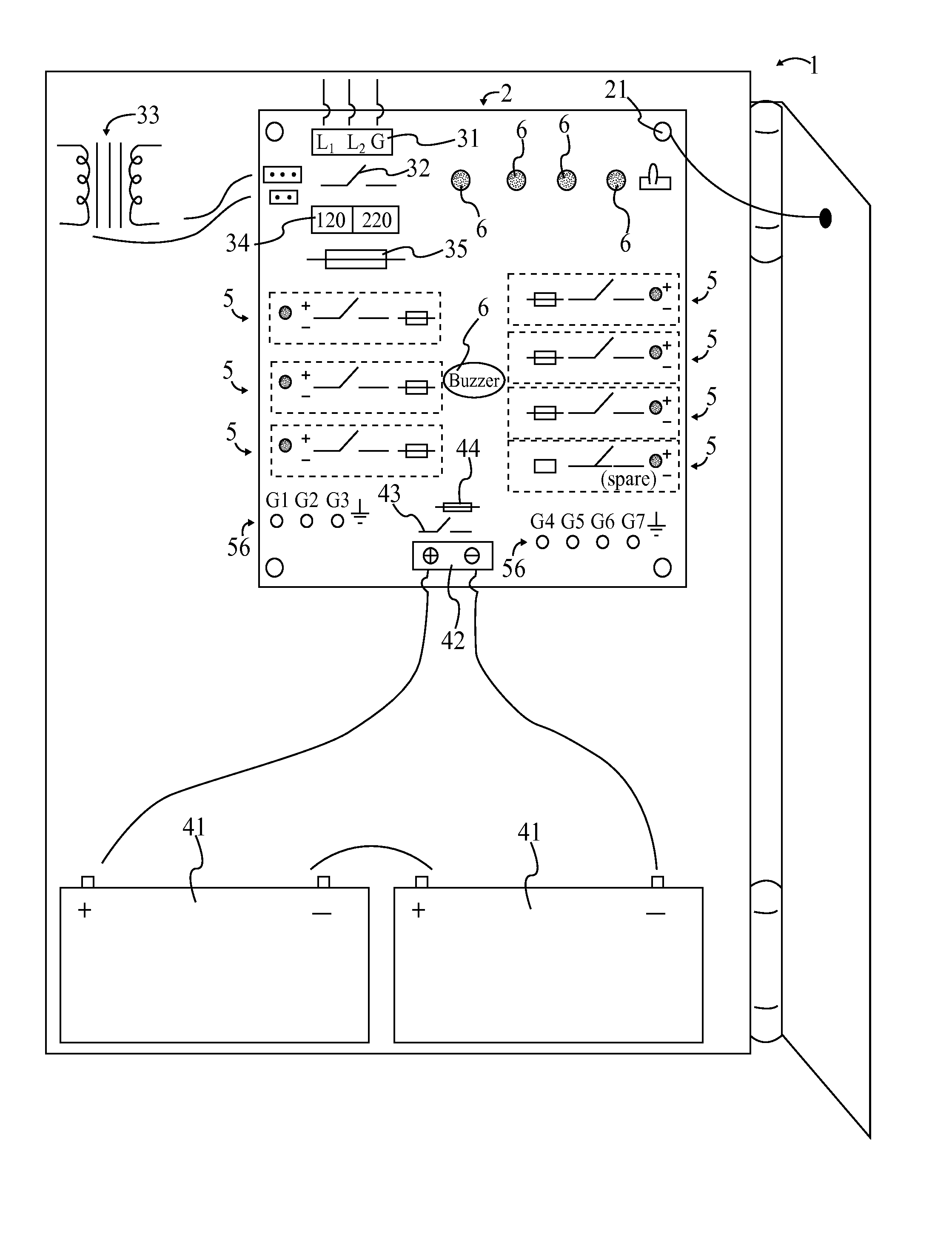
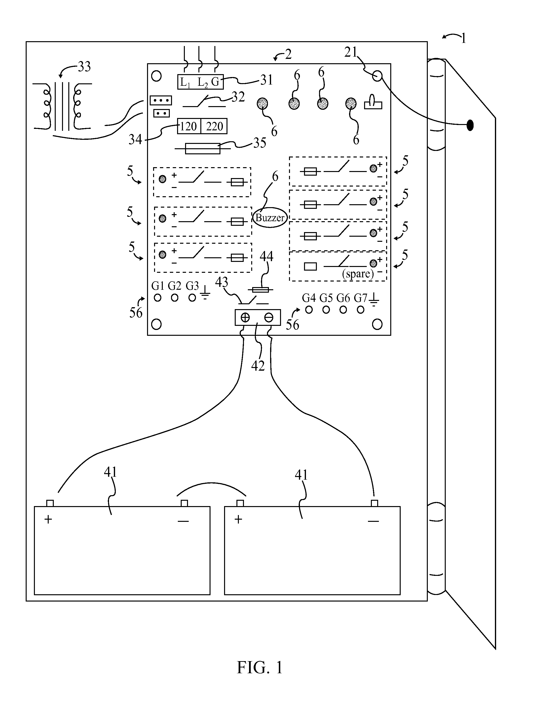
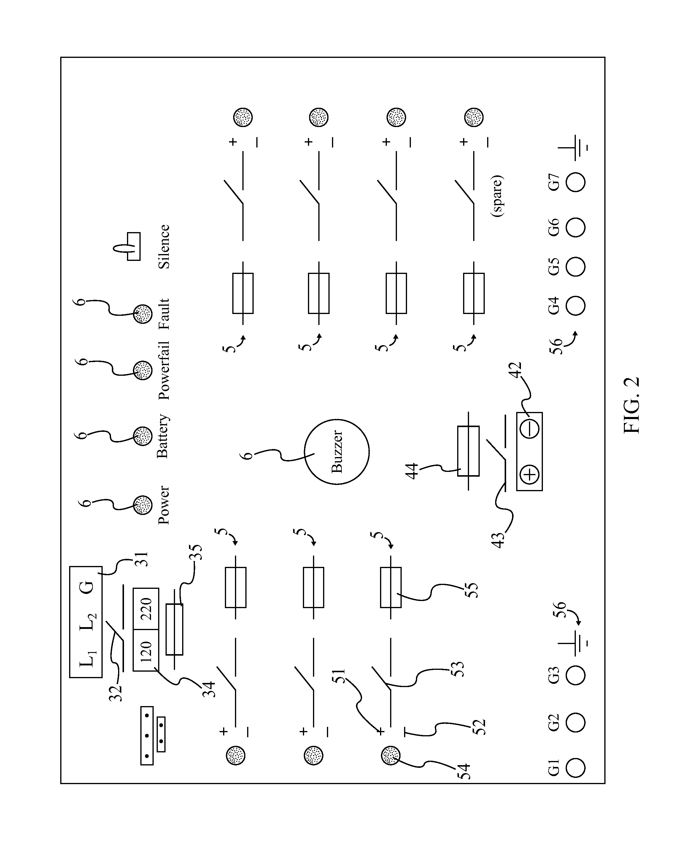
[0013]All illustrations of the drawings are for the purpose of describing selected versions of the present invention and are not intended to limit the scope of the present invention.

[0014]The present invention is a lighting control module that comprises an enclosure 1 and a circuit board 2. The present invention serves as a centralized control interface for a number of lights, providing a simple, safe, and power efficient apparatus that can be operated by the average person. The present invention draws from the basic concept of a distribution board, to which a number of improvements are introduced. The enclosure 1 acts as both a housing and electrical ground path for a number of components of the present invention while the circuit board 2 secures many of the electrical components of the present invention. The circuit board 2 is mounted to the enclosure as shown in FIG. 1, with the circuit board 2 being individually depicted in FIG. 2. In addition to the enclosure 1 and the circuit ...


PUM


Abstract

A lighting control module provides an enclosure for a circuit board, with the circuit board being mounted to and grounded to the enclosure. A primary power system is provided to receive and transmit voltage to lighting circuits, utilizing a terminal bus bar, a main switch, a voltage selection switch, and a transformer. An auxiliary power system draws energy from portable power sources in the event of a main power source failure. The auxiliary power system includes an associated terminal bus bar and an auxiliary switch. The primary and auxiliary power systems are connected to the lighting circuits through a circuit protection unit, e.g. fuse. The lighting circuits have both positive and negative terminals, LED indicators, switches, and individual fuses. The lighting circuits can be turned on and off individually by virtue of the switches for each lighting circuit. Status indicators and ground terminals are also provided.

Description

[0001]The current application claims a priority to the U.S. Provisional Patent application Ser. No. 61 / 842,183 filed on Jul. 2, 2013.FIELD OF THE INVENTION[0002]The present invention relates generally to a printed circuit board for a lighting system. The printed circuit board is safe, easy to operate, increases efficiency, and is housed within an enclosure such as a panel box.BACKGROUND OF THE INVENTION[0003]Fuse boxes are a common installation, seen in both commercial and residential sectors. These fuse boxes provide a convenient, single access, and overall safe apparatus that allows the common person to handle tripped fuses through a simple system of switches. Lighting systems, which are even more ubiquitous, are commonly installed as individual units. That is, each light is operated by its own switch, and is difficult to isolate electrically. There is a need for a centrally controlled lighting system which is easily and safely operated.[0004]It is therefore an object of the prese...

Claims


Application Information

Patent Timeline
Patent Type & Authority Patents(United States)
IPC IPC(8): H02J9/02H05B37/02H02J9/06
CPCH05B37/0209H05B47/10
Inventor RAY, COREY D.
Owner DC ENERGY SYST
Features
  • R&D
  • Intellectual Property
  • Life Sciences
  • Materials
  • Tech Scout
  • Unparalleled Data Quality
  • Higher Quality Content
  • 60% Fewer Hallucinations
Learn More