Friction stir welding apparatus

a friction stir welding and stir technology, applied in non-electric welding apparatuses, manufacturing tools, welding/soldering/cutting articles, etc., can solve the problems of scalable configuration, complicated configuration of friction stir welding tools, and unnecessary displacement of welding tools, so as to reduce the number of welding tools. , the effect of simple configuration

Active Publication Date: 2016-06-07
F TECH INC
View PDF18 Cites 2 Cited by
  • Summary
  • Abstract
  • Description
  • Claims
  • Application Information

AI Technical Summary

Benefits of technology

[0009]Therefore, under present circumstances, a friction stir welding apparatus having a new configuration that is simple, has high application scalability, and can weld a processing target member accurately along a predetermined processing direction has been desired.
[0020]According to the configuration in the fifth aspect of the present invention, by providing the auxiliary support mechanism fitted on the arm so as to support the mounting member by a support member and auxiliary support only the vertical position of the processing target member, the probe and the processing target member can be positioned more accurately, and the processing target member can be welded more accurately along the predetermined processing direction.

Problems solved by technology

However, because the friction stir welding tool needs to include the friction stirring stator having the guide portions, the configuration itself of the friction stir welding tool becomes complicated.
With this configuration, because a part of the friction stirring probe comes in contact with a rear surface of the guide portion of the friction stirring stator and rotates, a lubricating film and a hard alloy layer need to be added to the contact portion, thereby making the configuration itself of the friction stir welding tool complicated.
Furthermore, the configuration can be applied in a limited manner to a case where the contact portions of the pair of plate members are friction stir welded to form a fillet portion, and is not a scalable configuration that can perform friction stir welding with respect to a portion to be welded in other configurations.

Method used


Image

  • Friction stir welding apparatus
  • Friction stir welding apparatus
  • Friction stir welding apparatus

Examples


Embodiment Construction

[0024]A friction stir welding apparatus according to an embodiment of the present invention is explained in detail below with reference to the accompanying drawings. In the drawings, an x-axis, a y-axis, and a z-axis form three-axis orthogonal coordinates. A plane formed by the x-axis and the y-axis is parallel to a horizontal plane, and a normal direction of the z-axis is an upward direction.

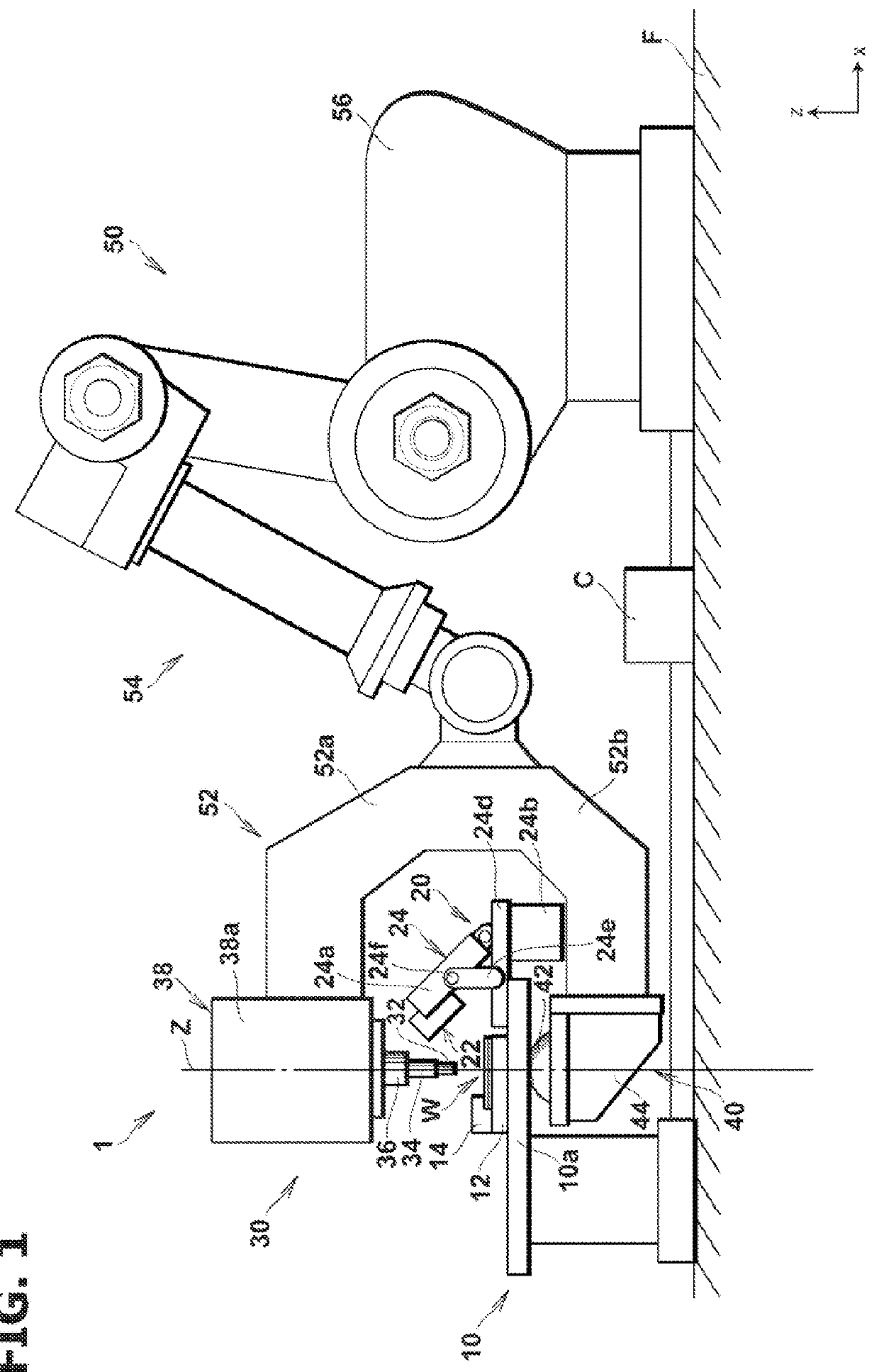
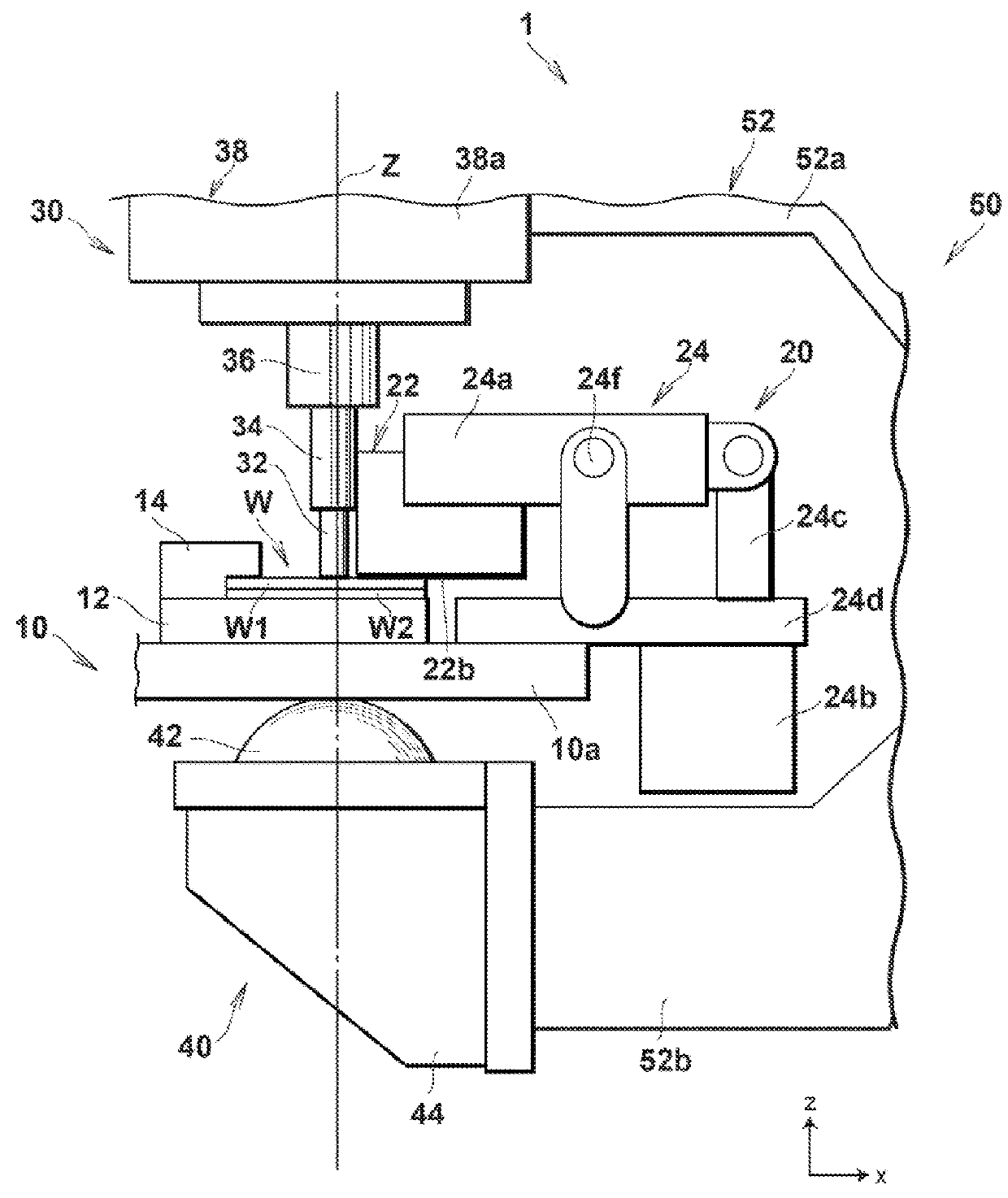
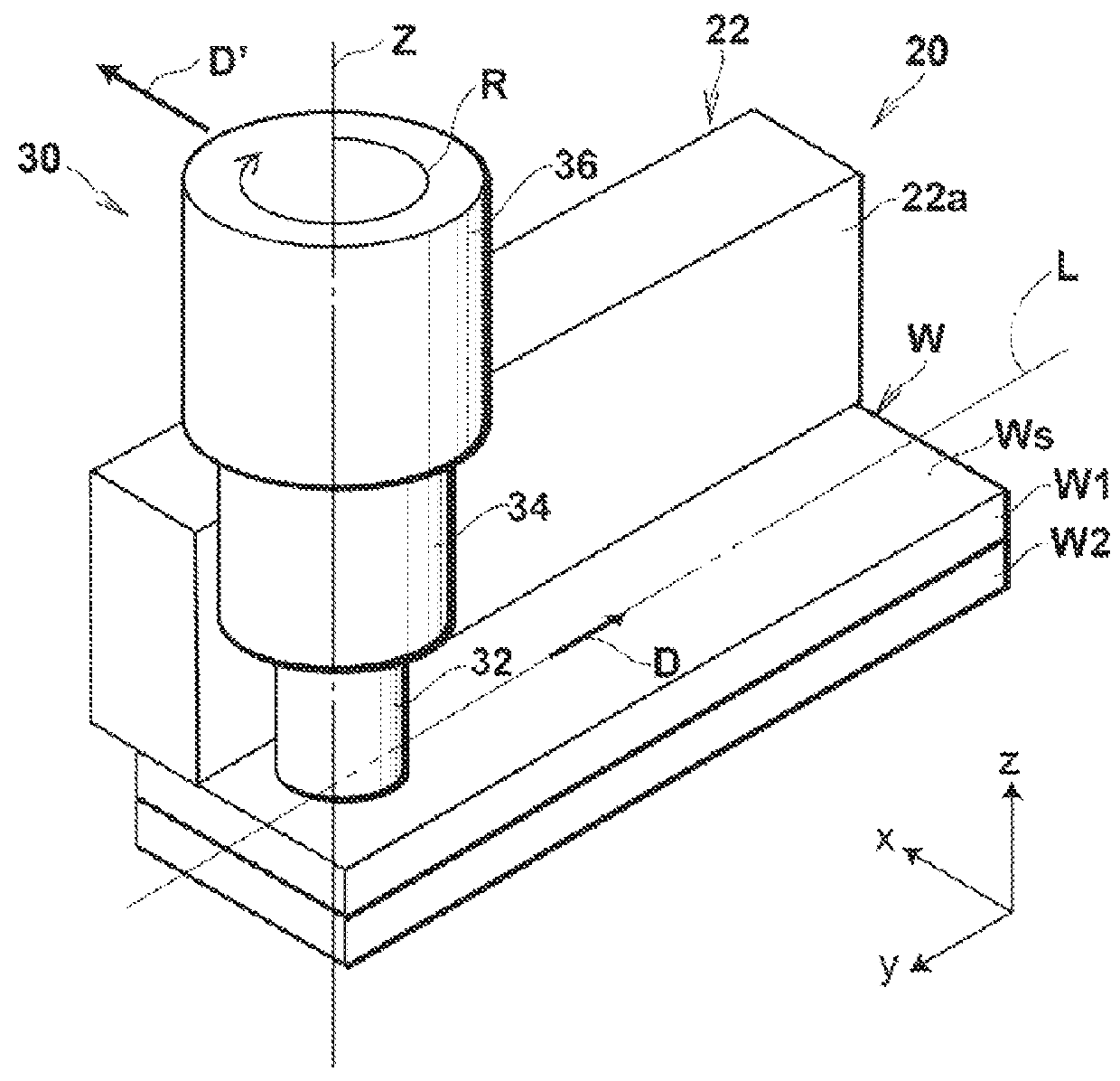
[0025]FIG. 1 is a side view showing an entire configuration of the friction stir welding apparatus according to the present embodiment. FIG. 2 is a partially enlarged side view of the friction stir welding apparatus according to the present embodiment. FIG. 3 is a partially enlarged perspective view of the friction stir welding apparatus according to the present embodiment.

[0026]As shown in FIGS. 1 to 3, a friction stir welding apparatus 1 includes a mounting table 10 fixedly installed on a floor F so that a processing target member W is mounted thereon, a correction mechanism 20 arranged on th...


PUM

PropertyMeasurementUnit
speedaaaaaaaaaa
strengthaaaaaaaaaa
relative displacementaaaaaaaaaa

Abstract

A friction stir welding apparatus has a probe rotatable and vertically movable with respect to a processing target member, a welding tool having an interposed member that covers a part of an outer periphery of the probe and is rotatable relative to the probe, a mounting member on which the processing target member is mounted, a movement mechanism having an arm fitted with the welding tool that can move the welding tool with respect to the processing target member by moving the arm, and a correction mechanism having a correction member that can correct a moving direction of the welding tool so as to be matched with a predetermined processing direction, by bringing the interposed member into contact with the processing target member when the welding tool is moved with respect to the processing target member by moving the arm, and fixed to the mounting member.

Description

BACKGROUND OF THE INVENTION[0001]The present invention relates to a friction stir welding apparatus, and more particularly relates to a friction stir welding apparatus that can weld a processing target member accurately along a predetermined processing direction.[0002]In recent years, there has been proposed a friction stir welding apparatus that performs friction stirs on a predetermined portion to be welded in a processing target component formed by a plurality of metal plates such as aluminum plates by a probe rotating at a high speed to weld the metal plates with each other. Even in a strength component of a movable body such as an automobile, a configuration having a welding portion welded by a friction stir welding apparatus has been realized.[0003]In such a friction stir welding apparatus, the probe and the processing target component need to be moved relative to each other to weld a predetermined portion to be welded accurately. Accordingly, it is important to move the probe...

Claims


Application Information

Patent Timeline
Patent Type & Authority Patents(United States)
IPC IPC(8): B23K20/12
CPCB23K20/1245B23K20/1255B23K2203/10B23K20/126B23K2103/10B23K20/1265
Inventor SAITOU, TOMOYA
Owner F TECH INC
Why Eureka
Try Eureka