Electronic device

a technology of electronic devices and housings, applied in the direction of electromechanical transducers, loudspeakers, transducer diaphragms, etc., can solve the problem of not taking into account the vibration of the panel attached to the housing

Active Publication Date: 2016-06-07
KYOCERA CORP
View PDF10 Cites 20 Cited by
  • Summary
  • Abstract
  • Description
  • Claims
  • Application Information

AI Technical Summary

Benefits of technology

[0080]One or both of the first and the second joining member s may inhibit water or dust from entering space between the panel.

Problems solved by technology

A problem posed when the panel attached to the housing is vibrated is not taken into consideration.

Method used


Image

  • Electronic device
  • Electronic device
  • Electronic device

Examples


first example

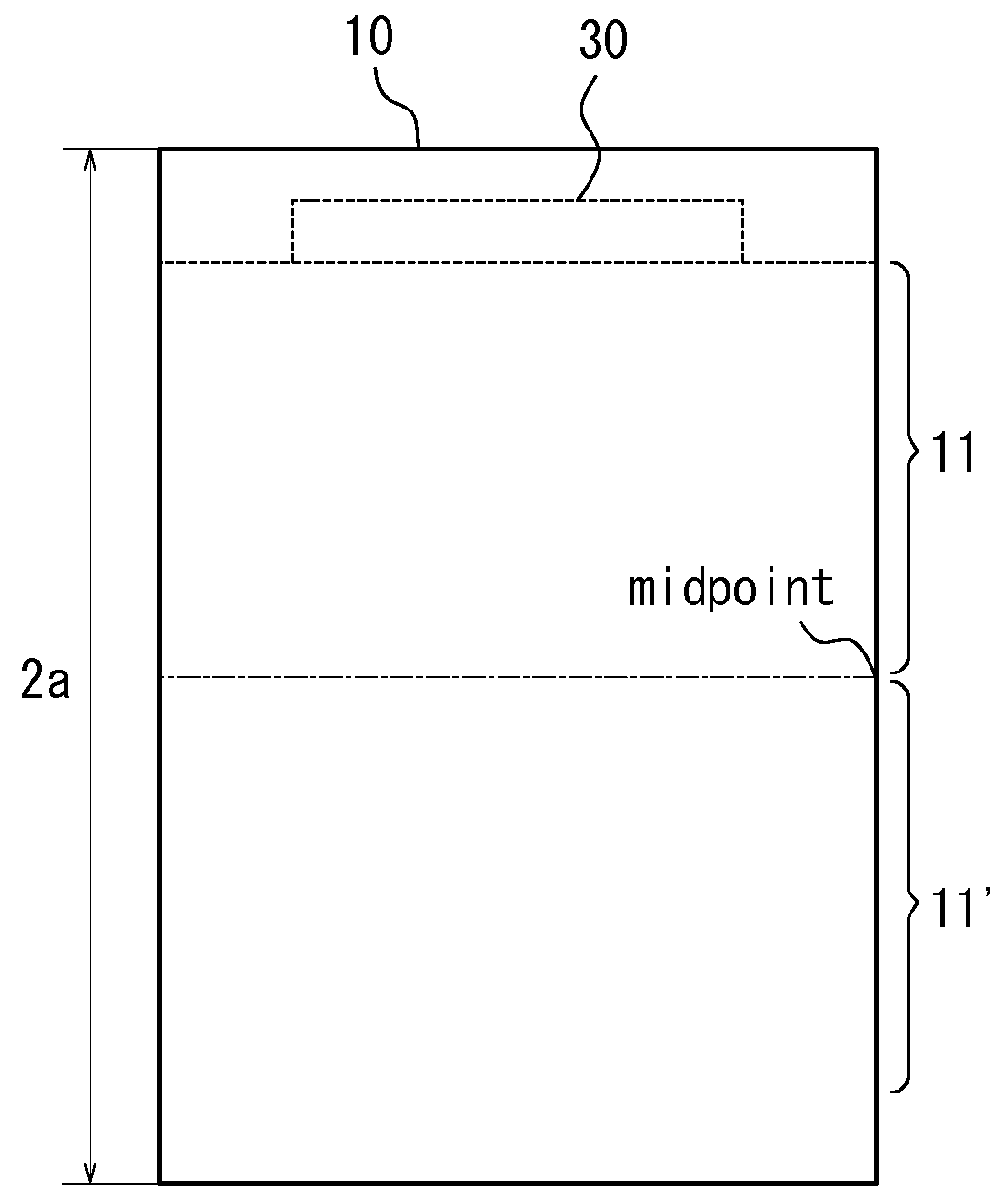
[0155]FIGS. 7A-7B are diagrams illustrating a first example. In the first example, the electronic device 100 has the support 42 for supporting the panel 10 in the area 11′ different from the contact area 11, but has no support at the contact area 11 for supporting the panel 10 with an elastic force greater or equal to that of the support 42. For example, as illustrated in FIGS. 7A and 7B, a part of the support 42 is not provided at the contact area side 11. Preferably, as illustrated in FIG. 7A, a side of the upper end portion nearest to the piezoelectric element 30 may be omitted. Alternatively, as illustrated in FIG. 7B, a portion of one side of the upper end portion also may be omitted. The position of the portion to be omitted is preferably a portion closest to the piezoelectric element 30, but not limited to the example described here. Further, the length of the portion is preferably greater than or equal to the length in the longitudinal direction of the piezoelectric element ...

second example

[0160]FIG. 9 illustrates a schematic cross-sectional view in the longitudinal direction of the electronic device 1 in a second example. In the second example, the housing 60 has an elastic member (support 42) that supports the panel 10 from the interior member (display 20), and distance d90 between the housing 60 and the display 20 in the contact area 11 is smaller than the distance d92 between the housing 60 and the panel 10 in other region 11′. Thereby, when the panel 10 is attached, the pressure to compress the support 42, i.e. a sponge, is weakened at the contact area 11 comparing to the region 11′, and the pressure to be applied on the panel 10 from the support 42 as a reaction may be weakened. Therefore, the pressure from the housing 60 which attenuates vibrations from the piezoelectric element 30 may be reduced. Incidentally, in the second example, thickness of the support is assumed to be constant.

[0161]For more concrete example, the interior member (the display 20) has a su...


PUM


Abstract

An electronic device is provided with a housing, a piezoelectric element, and a panel, which is attached to the housing and has a contact area contacting a part of human body, configured to vibrate by the piezoelectric element to generate a vibration sound to be transmitted by vibrating the part of human body, such that pressure from inside of the housing at the contact area of the panel is smaller than pressure from inside of the housing at different area from the contact area. Thereby the sound pressure property is improved, and thus the electronic device preferably transmits air conduction sound and vibration sound.

Description

CROSS-REFERENCE TO RELATED APPLICATION[0001]This application claims priority to and the benefit of Japanese Patent Applications No. 2012-116060 filed on May 21, 2012, No. 2012-117003 filed on May 22, 2012, and No. 2012-115795 filed on May 21, 2012, the entire contents of which are incorporated herein by reference.FIELD[0002]The present invention relates to an electronic device that vibrates a panel by applying a predetermined electric signal (audio signal) to a piezoelectric element and that transmits air-conducted sound and vibration sound to a user by transmitting the vibration of the panel to the user's body.BACKGROUND ART[0003]Patent Literature 1 recites an electronic device, such as a mobile phone or the like, that transmits air-conducted sound and bone-conducted sound to a user. As the air-conducted sound, Patent Literature 1 recites a sound that is transmitted to the user's auditory nerve by air vibrations, caused by a vibrating object, that are transmitted through the extern...

Claims


Application Information

Patent Timeline
Patent Type & Authority Patents(United States)
IPC IPC(8): H04R1/02H04R7/04H04M1/03H04R17/00
CPCH04R1/028H04R7/045H04R2499/11H04M1/03H04R17/00H04R2400/03H04R2440/05H04R2440/07
Inventor OZASA, KENICHIMIZUNO, HAYATOYAHAGI, HIROTONAGOSHI, KEIICHIZAIMA, TSUTOMUKANAYAMA, KOUTATSUNAKAMURA, TOMOAKITOMIOKA, HIDEOMASUNAGA, TAKUJIINAGAKI, TOMOHIRO
Owner KYOCERA CORP
Why Eureka
Try Eureka