Object information acquiring apparatus

a technology of object information and acquisition apparatus, which is applied in the field of object information acquisition apparatus, can solve the problems of increasing the number of elements in the two-dimensional transducer array, reducing the resolution, and prolonging the scanning time, so as to achieve the effect of enlarge the imaging range without reducing the resolution

Active Publication Date: 2016-06-14
CANON KK
View PDF20 Cites 1 Cited by
  • Summary
  • Abstract
  • Description
  • Claims
  • Application Information

AI Technical Summary

Benefits of technology

[0025]According to the present invention, it is possible to enlarge an imaging range without reducing a resolution in the object information acquiring apparatus for carrying out an image construction through a synthetic aperture.
[0026]Further features of the present invention will become apparent from the following description of exemplary embodiments with reference to the attached drawings.

Problems solved by technology

In order to carry out the three-dimensional electronic scanning over a wide range of imaging region with a high resolution, however, there are problems in that the number of the elements in the two-dimensional transducer array is increased, a processing scale is increased with the increase in the number of the elements, a scanning time is prolonged, and the like.
For this reason, it is hard to constitute a practical ultrasound diagnostic imaging apparatus.

Method used


Image

  • Object information acquiring apparatus
  • Object information acquiring apparatus
  • Object information acquiring apparatus

Examples


example 1

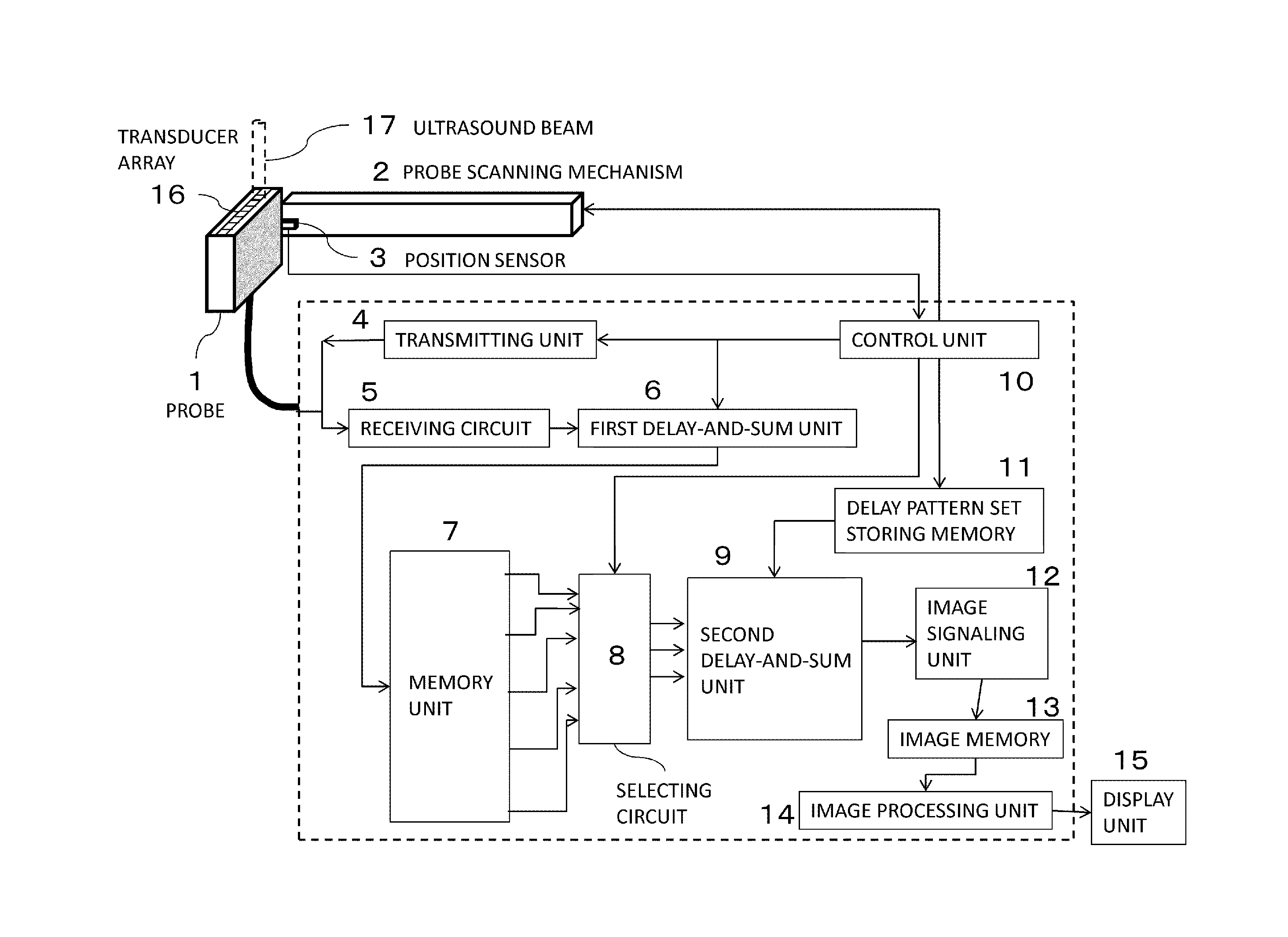
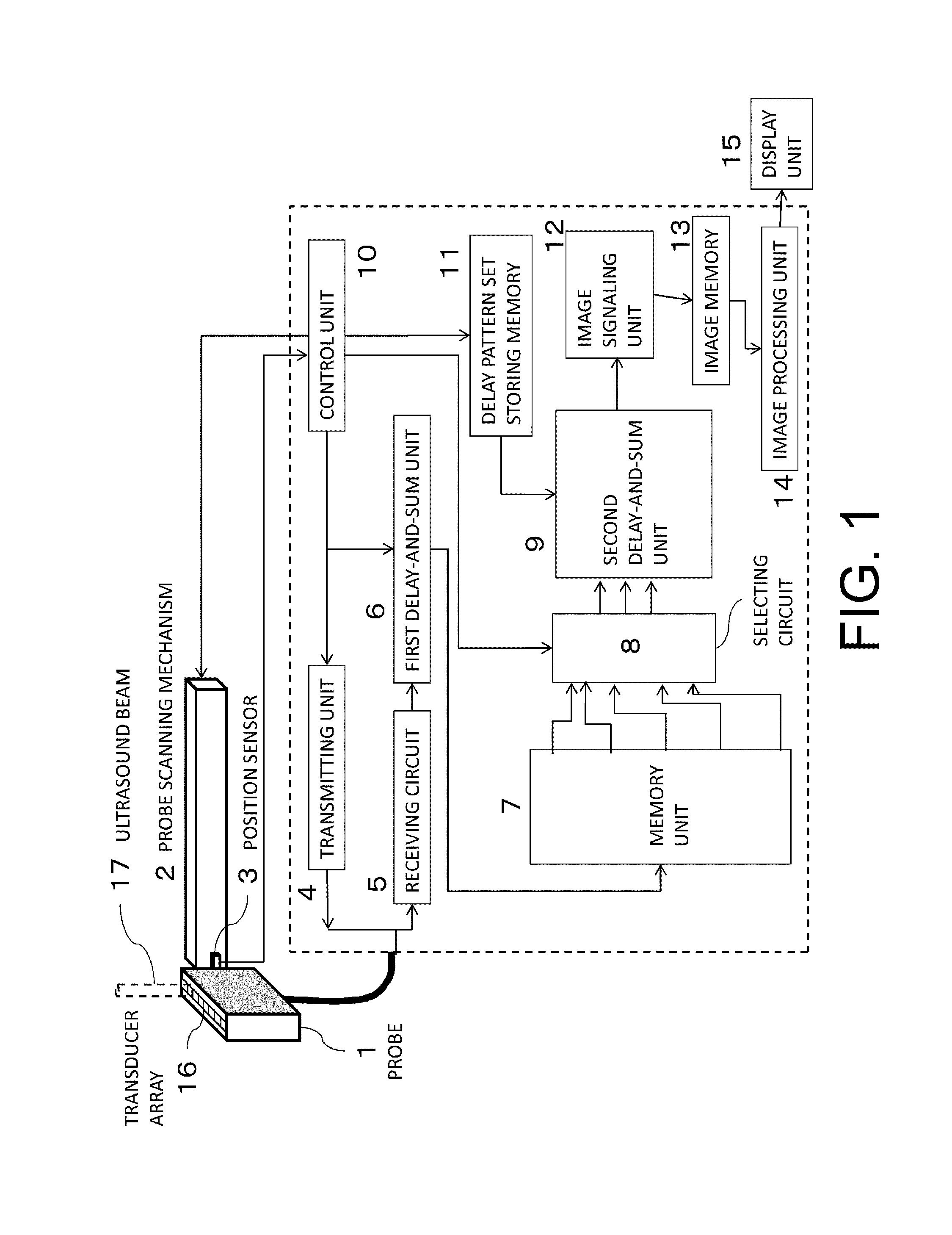
[0039]FIG. 1 shows a structure of an ultrasound diagnostic imaging apparatus based on the present invention. The apparatus includes a probe 1, a probe scanning mechanism 2, a position sensor 3, transmitting unit 4 (a transmitting circuit), a receiving circuit 5, a first delay-and-sum unit 6, memory unit 7, a selecting circuit 8, and a second delay-and-sum unit 9. The apparatus also includes control unit 10, a memory 11 for storing plural sets of delay patterns, image signaling unit 12, an image memory 13, image processing means 14 and display unit 15. Moreover, the reference numeral 16 denotes a transducer array included in the probe 1, and the reference numeral 17 denotes a conceptual view showing an ultrasound beam transmitted / received to / from the transducer array.

[0040]The present invention does not need to always include the display unit 15 such as an LCD or the image processing means 14. The present invention can also be constituted as an image acquiring apparatus having a func...

example 2

[0144]Example 2 employs a suitable structure for the case in which the mechanical scanning of the probe 1 is performed by the step and repeat method. In the present example, the first to third control phases to be carried out by the control unit 10 include the stop or start of the movement of the probe in the mechanical scanning of the probe 1.

[0145]FIG. 8 is a flow chart showing a control processing according to the present example. With regard to a structure of an apparatus and the details of a processing which are common to Example 1, description will be omitted.

[0146]At Steps S801 to S805, the same processing as Example 1 is carried out. More specifically, the electronic scanning is carried out with the movement of the probe 1 until a predetermined number M of sectional slice surfaces for performing a synthetic aperture in an elevation direction are acquired. Thus, the ultrasound received beam signal 29 is acquired. The ultrasound received beam signals 29 thus acquired are store...

example 3

[0154]In Example 3, controls having different ultrasound transmitting pattern conditions for acquiring an ultrasound echo signal are carried out in the first to third control phases to be performed by the control unit 10. In the present example, furthermore, the transducer array provided on the probe 1 has a 1.5D, 1.75D or 2D structure. By using the transducer arrays, it is possible to control a transmitting beam pattern in the elevation direction. Moreover, the present example has a feature that different controls are carried out in the first to third control phases to be performed through the control unit 10 by using the ultrasound transmitting pattern conditions in order to change the transmitting beam pattern in the elevation direction.

[0155]First of all, description will be given to a change in the transmitting pattern in the elevation direction using the probe 1 according to the present example. In the present example, as an almost one-dimensional transducer array, there is us...


PUM


Abstract

There is used an object information acquiring apparatus including a probe for electrically scanning an object in first direction and mechanically scanning in second direction intersecting with the first direction, a first delay-and-sum unit for operating a delay-and-sum on a received signal, a memory for storing a first delay-and-sum signal for each plane in the second direction, a selecting unit for selecting signals corresponding to M sectional planes from among the stored signals, a second delay-and-sum unit for operating a delay-and-sum on the selected signals in the second direction, and a unit for acquiring image in the object from the second delay-and-sum signal, the second delay-and-sum unit switching, according to the mechanical scanning, a first case in which M signals are fixed and a delay pattern is varied and a second case in which a set of the M signals is varied and the delay pattern is fixed.

Description

TECHNICAL FIELD[0001]The present invention relates to an object information acquiring apparatus for carrying out a synthetic aperture.BACKGROUND ART[0002]As a powerful diagnostic imaging apparatus for early detecting a breast cancer, conventionally, an X ray mammography apparatus is widely known. On the other hand, a method of acquiring a wide range of three-dimensional image data by using a low invasive ultrasound echo in place of X rays accompanied by an exposure is disclosed in PTL1 (Patent Literature 1) or the like, for example. The PTL1 discloses an apparatus for acquiring a three-dimensional ultrasound echo image by carrying out electronic scanning while mechanically moving an ultrasound probe (which will be hereinafter also referred to as a probe).[0003]As a method of acquiring a three-dimensional ultrasound echo image, there is well known a method of carrying out three-dimensional electronic scanning by using a two-dimensional transducer array in which elements are arranged ...

Claims


Application Information

Patent Timeline
Patent Type & Authority Patents(United States)
IPC IPC(8): A61B5/00G01S15/89A61B5/06G01S7/52A61B8/00A61B8/08
CPCG01S7/52085G01S15/8927G01S15/8945G01S15/8993G01S15/8997A61B5/0033A61B5/066A61B8/483G01S15/8918A61B8/4477A61B8/145
Inventor OIKAWA, KATSUYAYODA, HARUO
Owner CANON KK
Why Eureka
Try Eureka