Lighting device for vehicle

a technology for lighting devices and vehicles, applied in fixed installations, lighting and heating equipment, cycle equipment, etc., can solve problems such as production costs increasing, and achieve the effects of enhancing the external appearance reducing the light emitting area of the lighting device, and reducing production costs

Active Publication Date: 2016-06-14
HONDA MOTOR CO LTD
View PDF11 Cites 2 Cited by
  • Summary
  • Abstract
  • Description
  • Claims
  • Application Information

AI Technical Summary

Benefits of technology

[0004]However, when a structure is provided as in Japanese Patent No. 4437952, in which a vehicle cover, such as the aforementioned mud cover, is used to cover a harness that extends from the board, the light emitting area of the lighting device is reduced. On the other hand, in the case that the harness is covered by a vehicle cover while attempting to preserve the light emitting area of the lighting device, a structure may be considered in which the board on which the light emitting diodes are mounted is made larger, whereas the harness is connected at a position separated a given distance from the light emitting diodes, and then is covered by the vehicle cover. However, in this case, there is a possibility for other problems to occur in that, due to the fact that the board is made larger in size, production costs increase, and the lighting device is made larger in scale, which contravenes the goal of enhancing the external appearance of the lighting device.
[0005]The present invention has been made taking into consideration the aforementioned situation, and has the object of providing a vehicular lighting device, which is capable of enhancing the external appearance of the lighting device by concealing the visibility of a harness connected to a light emitting diode board with a simple structure, while also sufficiently preserving the light emitting area when light is irradiated therefrom.

Problems solved by technology

However, in this case, there is a possibility for other problems to occur in that, due to the fact that the board is made larger in size, production costs increase, and the lighting device is made larger in scale, which contravenes the goal of enhancing the external appearance of the lighting device.

Method used


Image

  • Lighting device for vehicle
  • Lighting device for vehicle
  • Lighting device for vehicle

Examples


Embodiment Construction

[0035]A vehicular lighting control device according to a preferred embodiment of the present invention will be described in detail below with reference to the accompanying drawings.

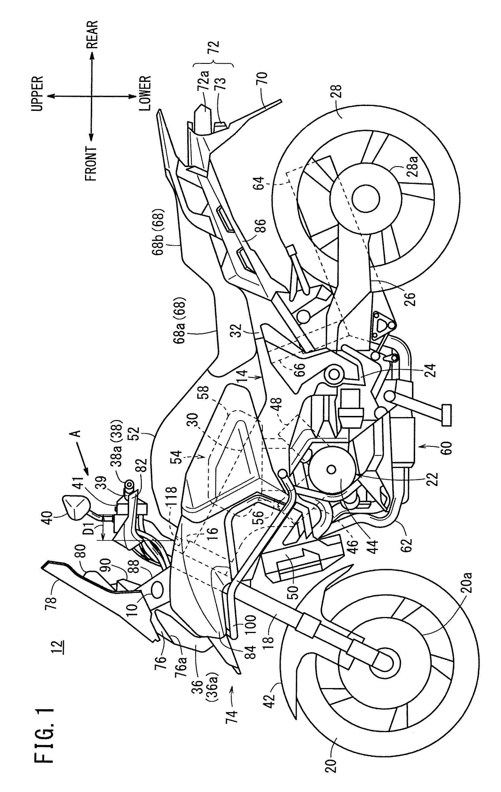
[0036]FIG. 1 is a schematic side elevational view of a saddle-type motorcycle (hereinafter also referred to as a “motorcycle”) 12, which incorporates therein a vehicular lighting control device (winker lamp) 10 according to an embodiment of the present invention. The present invention will hereinafter be described in detail below as applied to a saddle-type motorcycle. However, the principles of the present invention are not limited to a saddle-type motorcycle, but also are applicable to any of various other land vehicles, including other types of powered two-wheeled vehicles, motor-assisted bicycles, and powered four-wheeled vehicles. For easier understanding of the present invention, forward, rearward, upward, and downward directions will be described with respect to the directions indicated by the arro...


PUM


Abstract

In the present invention, an inner lens of a turn signal lamp is provided with: a lens cut part that inhibits the transmission of light travelling, when seen in a front view, linearly from a substrate toward an outer lens; a projection part that projects toward an LED; and an eave part that extends from the base end side of the projection part inwardly in the vehicle width direction. A harness that is electrically connected with the LED is connected to the substrate through a partial space that is surrounded by the substrate, the projection part, and the eave part.

Description

TECHNICAL FIELD[0001]The present invention relates to a vehicular lighting device (lighting device for vehicle) that employs light emitting diodes as a light source.BACKGROUND ART[0002]Heretofore, with a lighting device that employs light emitting diodes, in order to enhance the external appearance (aesthetic appearance) thereof, a structure has been provided in which wires (harnesses) for supplying power to the light emitting diodes are hidden from view.[0003]For example, in Japanese Patent No. 4437952, a tail lamp structure is disclosed in which light emitting diodes are applied as a light source. As shown in FIG. 8 of Japanese Patent No. 4437952, a light emitting diode board (board) on which light emitting diodes are mounted is attached to a housing (base), and a harness, which is connected to the board, extends from a lower side of the base. In this case, a configuration is provided so that the harness cannot be seen from the exterior, by means of a mud cover that is laid over t...

Claims


Application Information

Patent Timeline
Patent Type & Authority Patents(United States)
IPC IPC(8): B62J6/00F21S8/10B60Q1/00B60Q1/38
CPCF21S48/25B60Q1/0088B60Q1/38B62J6/005F21S48/215F21S48/22F21S48/2206F21S48/236F21S43/14F21S43/20F21S43/27F21S43/315B60Q1/2657B62J6/055F21S43/50
Inventor TAKENAKA, NOBUYUKIKURIKI, DAISUKESODA, HAJIMETETSUKA, TAKASHI
Owner HONDA MOTOR CO LTD
Why Eureka
Try Eureka