Cooling tower with geodesic shell

a cooling tower and geodesic shell technology, applied in the direction of climate sustainability, industrial buildings, shrink coolers, etc., can solve the problems of reducing the efficiency of the cooling tower, the footprint of the cooling tower is a factor to consider, and the cubical shell is heavy relative to its footprint, so as to achieve better tonnage, reduce the effect of cooling tower footprint and reduce the footprin

Active Publication Date: 2016-06-14
ROSENWACH TANK CO
View PDF13 Cites 3 Cited by
  • Summary
  • Abstract
  • Description
  • Claims
  • Application Information

AI Technical Summary

Benefits of technology

[0032]A shell according to the present invention would not require an internal frame to support the panels, and may be at least 70% stronger than a cubical shell of the same height and footprint, which means it can be made lighter while handling the same volume of air as, for example, a cubical cooling water shell.
[0033]The geodesic appearance of a shell according to the present invention may be appealing, which is a benefit because the cooling tower would be visible on a roof from many vantage points.
[0034]A cooling tower with a shell according to the present invention may be more thermally efficient compared to a cooling tower with a cubical shell that processes a similar volume of water. This means that a tower according to the present invention may produce better Tonnage (BTU / hr) with the same or less GPM. In a system according to the present invention, the water supplied into the tower via an inlet pipe may be cooled in the basin pool since the inlet pipe resides in the basin pool before reaching the riser. Thus, the inlet water may be cooled (e.g. by about 5 degrees) and thereafter it may be further cooled as it is sprayed over the fill cells (e.g. by another 9 degrees).
[0035]The internal configuration of a shell according to the present invention may induce thermal condensation. The dome shape design may prevent water from escaping and may cause water to condense on its walls. The condensed water may be then returned to the basin pool. In a cubical tower, the fan only draws air in a vertical column toward the area covered by the fan and is believed by the inventor hereof to lose about 30% of the water without causing condensation.

Problems solved by technology

Furthermore, since a typical rooftop has a limited area for a cooling tower, the footprint of a cooling tower is a factor to consider.
Thus, cubical shells are heavy relative to their footprint.
Furthermore, cubical shells have corners that tend to trap heated air and reduce the efficiency of the cooling tower.

Method used


Image

  • Cooling tower with geodesic shell
  • Cooling tower with geodesic shell
  • Cooling tower with geodesic shell

Examples


Embodiment Construction

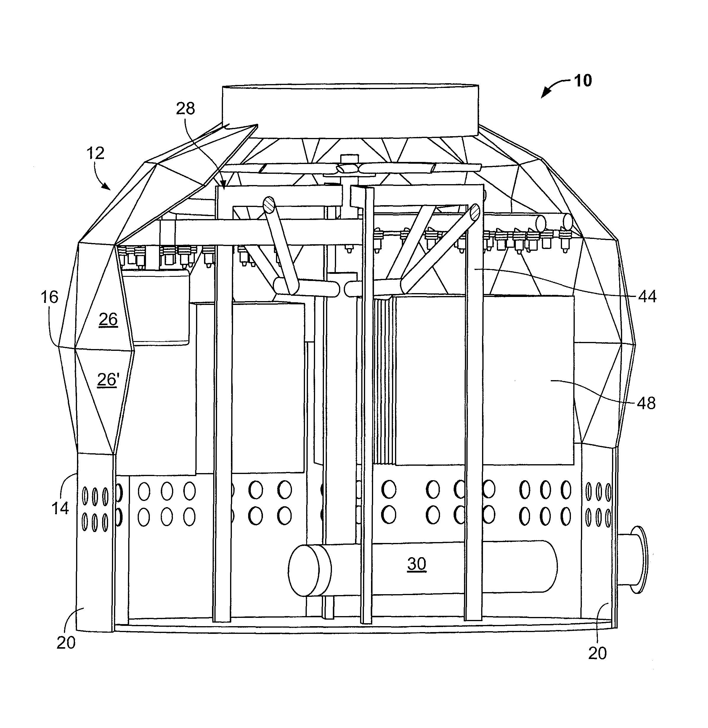
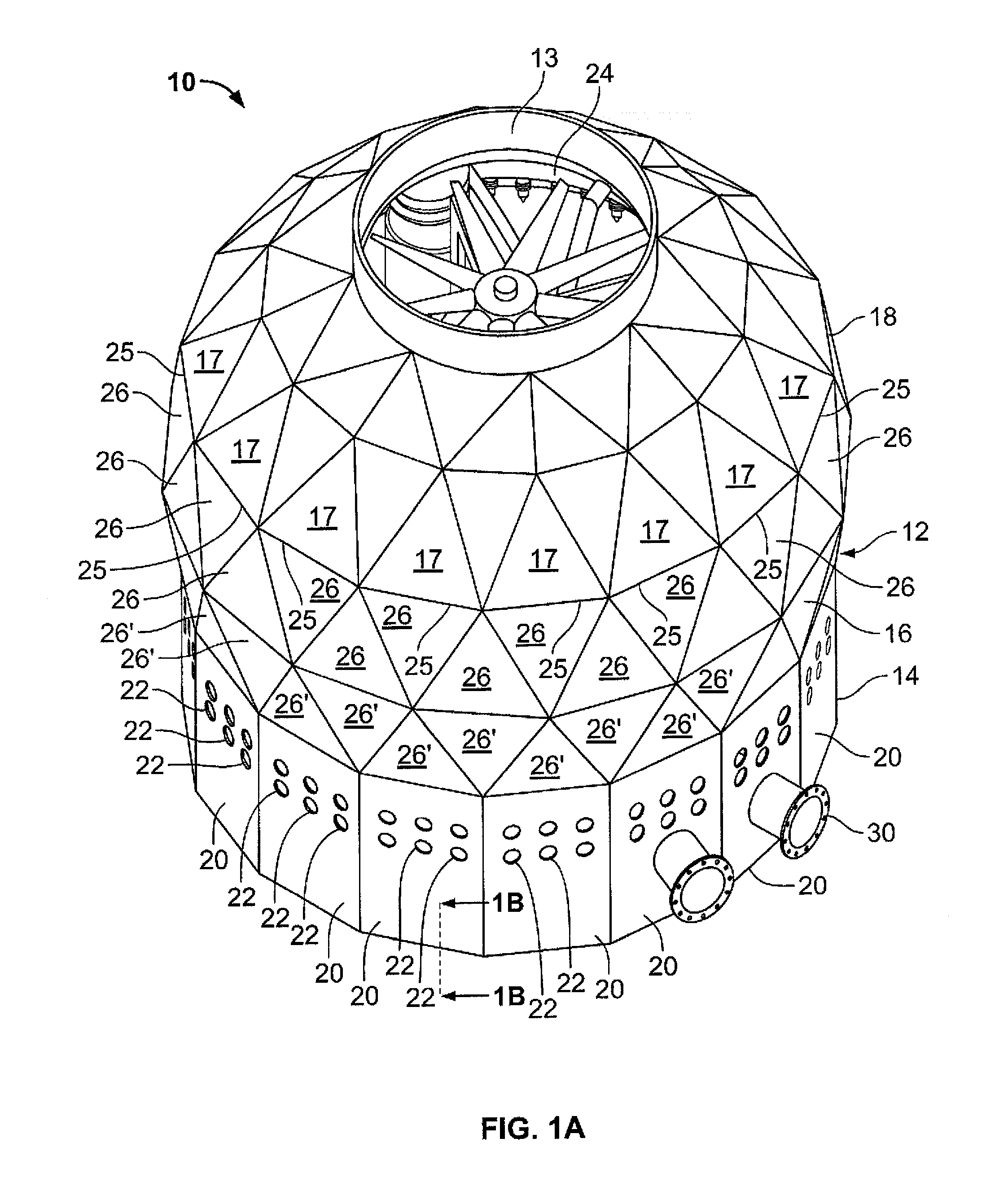
[0048]FIG. 1A depicts the exterior appearance of a cooling tower 10 according to a first embodiment of the present invention. Cooling tower 10 includes an exterior shell 12. Exterior shell 12 includes a base section 14, a cap section 18, an annular wall 16 residing between base section 14 and cap section 18. Annular wall 16 supports cap section 18 and is supported on base section 14.

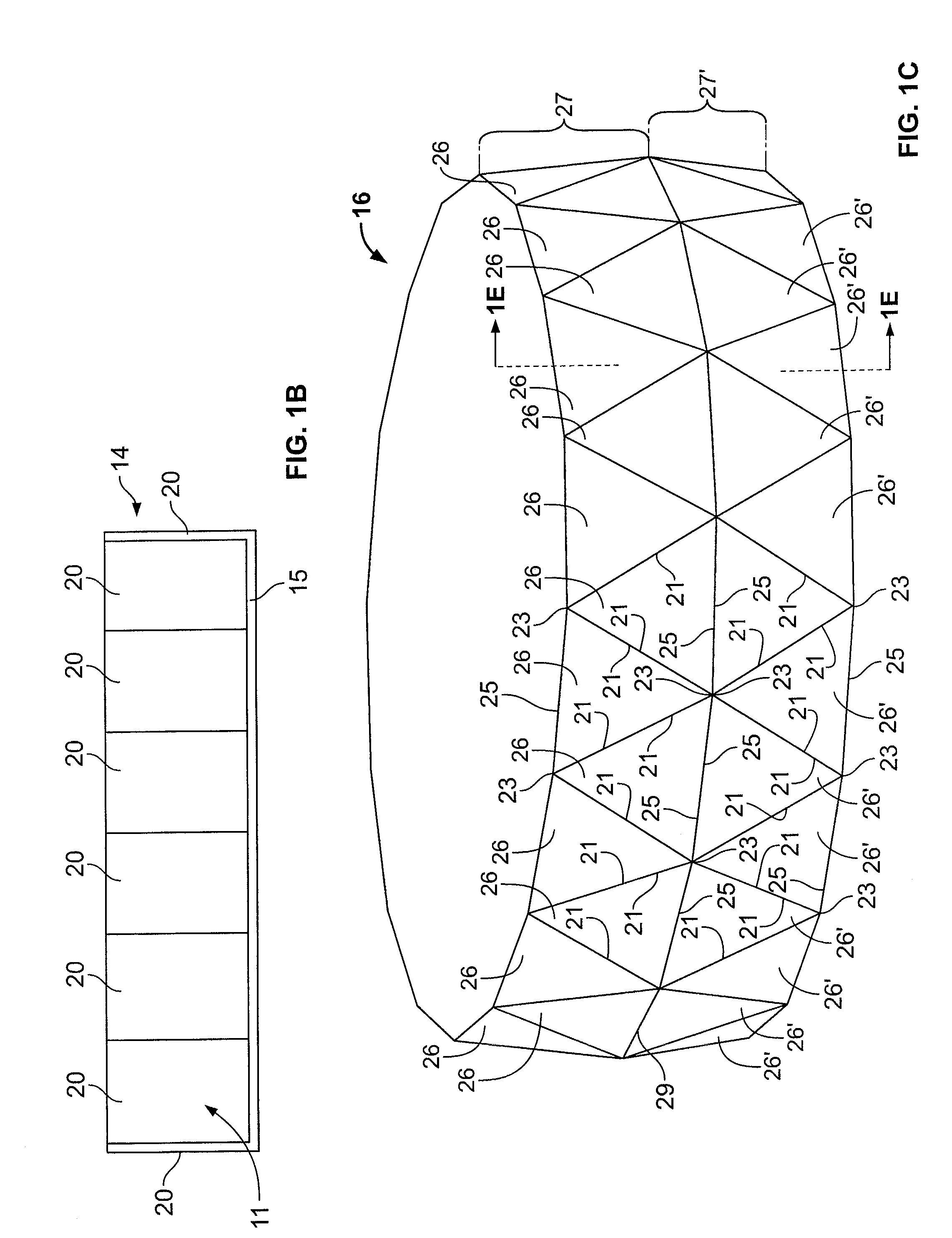
[0049]Base section 14 preferably includes a polygonal enclosure defined by a plurality of rectangular, planar panels 20. Preferably, panels 20 have the same shape and the same dimensions, and are joined along edges thereof to obtain a wall with a uniform height along its upper edge. A plurality of openings 22 are defined in panels 20 to allow air to pass from the exterior of shell 12 to the interior space thereof. In operation, openings 22 serve as air in-take passages.

[0050]Base section 14 may be joined to a bottom wall 15 to define a water-tight pool 11 that collects cooled water (see FIG. 1B) below op...


PUM


Abstract

A cooling tower with a self-supported shell, and a cooling apparatus residing inside the shell. The shell includes a base section, a cap section and an annular wall residing between the base section and the cap section, the annular wall including a plurality of geometric bodies that are joined to one another and giving the shell a geodesic configuration.

Description

CROSS REFERENCE TO RELATED APPLICATIONS[0001]The present application claims priority to U.S. Provisional Patent Application No. 61 / 920,598, filed Dec. 24, 2013, the entire contents of which are incorporated in full herein by reference.FIELD OF THE INVENTION[0002]The present invention relates to a cooling tower for a building and in particular to a cooling tower having an exterior shell constructed based on geodesic construction principles.BACKGROUND[0003]A conventional cooling tower includes a cooling apparatus enclosed within a shell.[0004]In a closed circuit cooling tower the cooling apparatus includes a cooling coil.[0005]In a closed circuit cooling tower, the condenser water is pumped through a coil and water from an outside source is distributed over the coil to cool the water inside the coil.[0006]In an open draft (induced draft) cooling tower the cooling tower does not include a coil.[0007]In an open draft cooling tower, the water from the condenser is conducted straight up t...

Claims


Application Information

Patent Timeline
Patent Type & Authority Patents(United States)
IPC IPC(8): E04H5/12F28C1/00F28F25/10F28F25/02
CPCF28C1/00E04H5/12F28F25/02F28F25/10Y02B30/70
Inventor ROSENWACH, ANDREW
Owner ROSENWACH TANK CO
Why Eureka
Try Eureka