Gas flow meter with horizontal piston movement

a technology of gas flow meter and piston movement, which is applied in the direction of measuring devices, instruments, and fluid speed measurement, can solve the problems of small leakage of fluid, introduction of measurement errors, etc., and achieve the effect of preventing piston damag

Inactive Publication Date: 2014-11-04
MESA LABORATORY
View PDF11 Cites 1 Cited by
  • Summary
  • Abstract
  • Description
  • Claims
  • Application Information

AI Technical Summary

Benefits of technology

[0011]The measurement errors listed above are reduced by several aspects of the disclosed device. First, the low mass piston accelerates faster, reducing compression of the fluid under measure. Second, the lower mass of the piston, possibly aided by the low friction coating, reduces friction between the piston and cylinder. And third, the leakage through the piston and cylinder clearance is reduced. This leakage is proportional to the fluid pressure required to displace the piston. By reducing the piston mass and friction and the effect of gravity, the pressure required to displace the piston is reduced. This reduces the leakage between the piston and cylinder, enhancing measurement and accuracy.
[0012]With the horizontal orientation of the piston, the piston can be made lighter than in the known flow meters. In prior vertical cylinders, the piston was required to have substantial mass in order to descend rapidly after being raised by the gas flow. Also less energy is required to move the piston horizontally. More data can be acquired, faster, than with the prior flow meters.
[0013]Thus, the flow meter can use a piston with a combination of low mass and low friction, which may require less than 0.002 psi of gas pressure to be displaced. With almost no pressure needed to displace the piston, the gas leakage around the piston becomes insignificant. The low mass piston thus has faster response time, and produces minimal pressure changes in the gas stream during the measurement cycle. With the faster response time and taking flow measurements in both directions as the piston translates between the measurement detectors, gas flow readings are obtained significantly faster than with previous flow meters.
[0018]When a single or initial measurement is started, if the piston is not detected by the left-detect sensor, the valves are sequenced to displace the piston to the left until the piston is detected. After piston detection a normal measurement cycle is started. The first left to right reading may be discarded to allow for flow stability. After measurement is started the piston reversal occurs at a set time delay after the piston reaches the end measurement sensor. The time delay interval is set for the time needed to reverse the piston direction and allow the piston movement to stabilize. The left-detect and right-detect optical detectors activate a piston reversal if the time delay interval is not reached, and also to prevent piston damage in cases of a measurement sensor failure.

Problems solved by technology

However, in these positive displacement piston flow meters, measurement errors can be introduced from the acceleration of the piston compressing the fluid under measurement as a measurement is initiated; friction between the cylinder and piston causing pressure variations as the flow is being measured; and clearance between the piston and cylinder resulting in a small leakage of fluid through this clearance.

Method used


Image

  • Gas flow meter with horizontal piston movement
  • Gas flow meter with horizontal piston movement
  • Gas flow meter with horizontal piston movement

Examples


Embodiment Construction

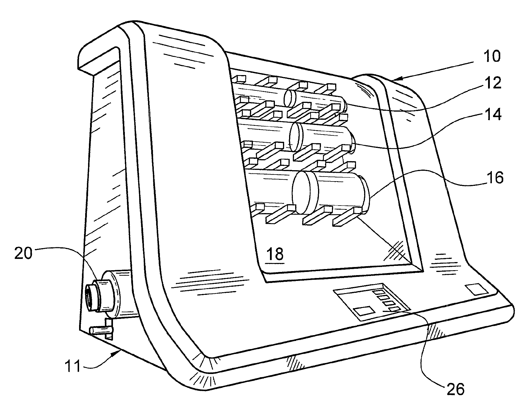
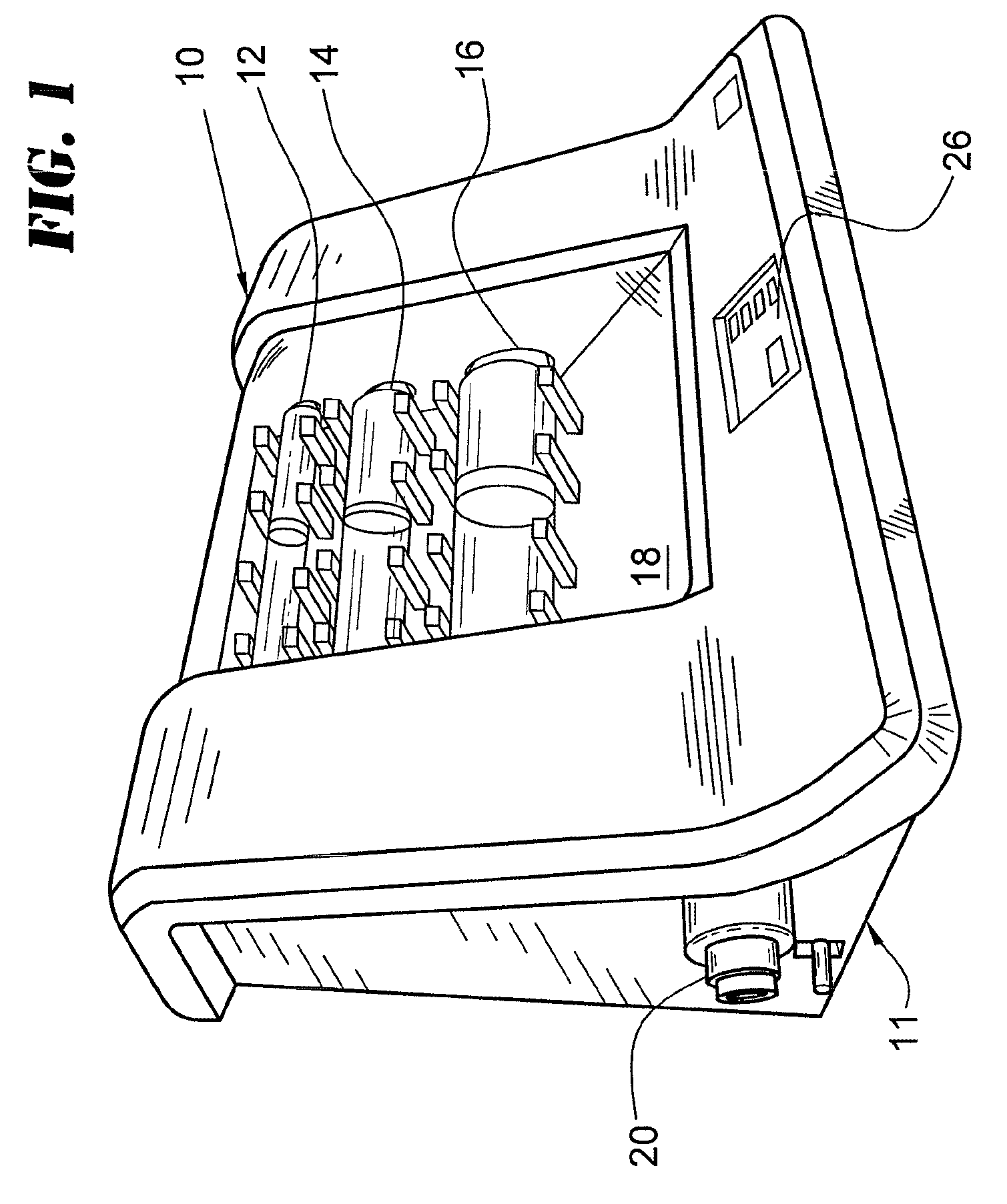
[0024]FIG. 1 is a perspective view of a flow meter 10, including three horizontal gas flow tubes 12, 14, 16 behind a viewing window 18, a pair of gas inlet / outlet ports 20, 22 (see FIG. 2), and a user interface 26 comprising an LED touch screen which accepts user inputs and reads out the flow readings.

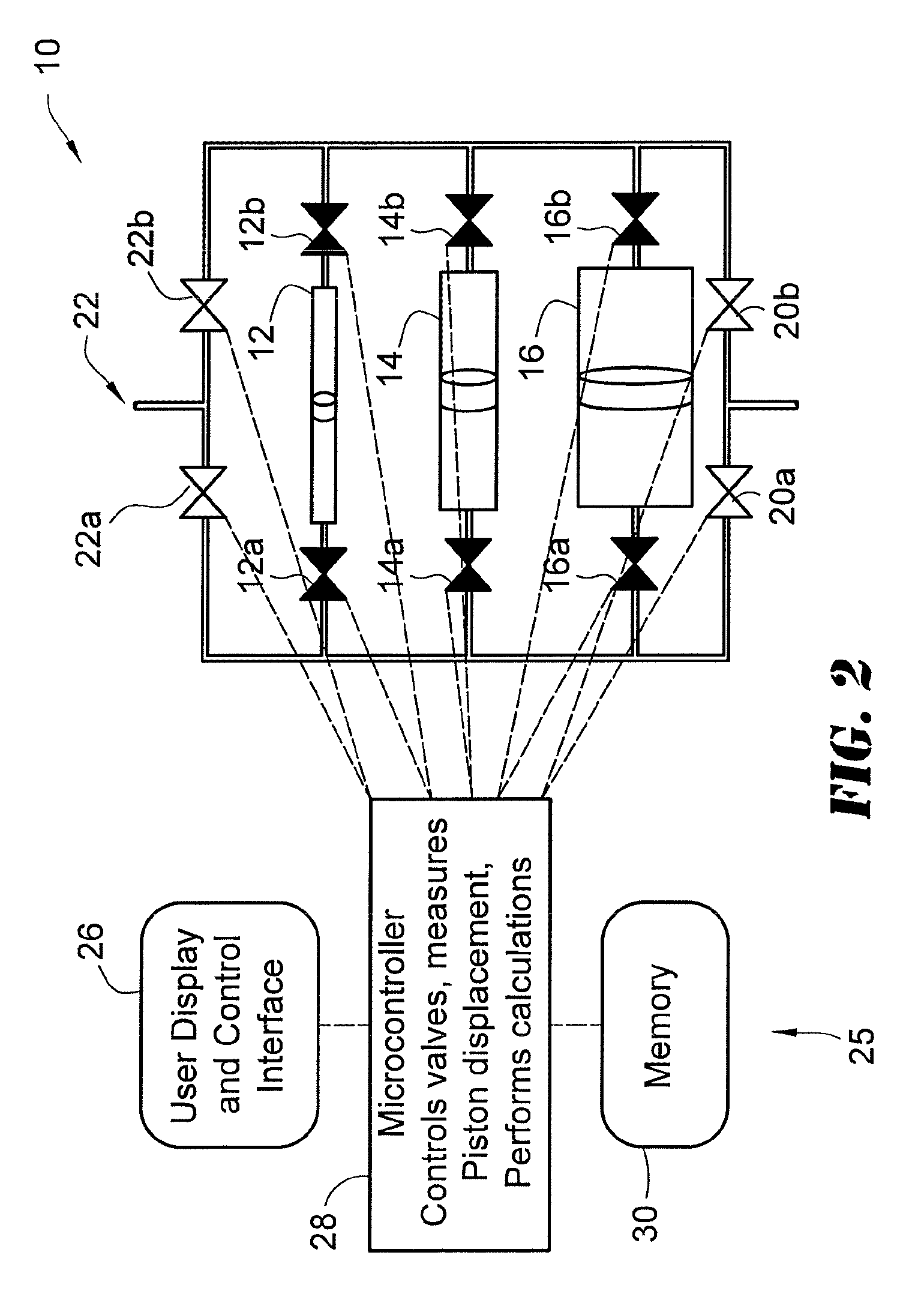
[0025]The three gas flow tubes 12, 14 and 16 and related hardware are shown schematically in FIG. 2. A control part 25 includes the user interface 26, and a microcontroller 28 with a memory 30. The tube 12 is for low flow, for example 5 to 500 ccm. The tube 14 is for medium flow, for example 500-5000 ccm. The tube 16 is for high flow, for example 5000-50000 ccm.

[0026]In another version, the largest tube and piston (˜51 mm diameter) measures flow rates from 50,000 ccm to 3,500 ccm. The medium tube and piston (˜24 mm diameter) measures flow rates from 5,000 ccm to 350 ccm, and the smallest tube and piston (˜10 mm diameter) measures flow rates from 500 ccm to 5 ccm. The overlapping of the...


PUM


Abstract

A method and a gas flow meter for measuring gas flow. A cylinder is supported in the flow meter with a horizontal orientation. A piston is disposed movably within the cylinder, the piston having a surface which forms a clearance seal with a surface of the cylinder. The piston may have a low-friction coating such as diamond-like carbon. A gas flow to be measured is received at a gas inlet, and directed to the cylinder so as to move the piston within the cylinder. The gas flow is directed by valves and conduits alternately to the two ends of the cylinder, for measuring the gas flow in both directions of the cylinder. From the detected movement of said piston electrical signals representative of the gas flow are generated.

Description

CROSS-REFERENCE TO RELATED APPLICATION[0001]This application claims priority to U.S. Provisional Application Ser. No. 61 / 499,880 filed on Jun. 22, 2011, and Ser. No. 61 / 501,856 field on Jun. 28, 2011, both incorporated by reference in their entireties.BACKGROUND OF THE INVENTION[0002]The present invention relates to a high accuracy positive displacement gas flow meter with horizontal piston movement. The flow meter may advantageously have a low mass piston, constructed of a rigid material such as glass or graphite. Advantageously, a low friction film outer coating of wear resistant material such as diamond-like carbon (DLC) may be formed on the piston.[0003]Positive displacement piston flow meter technology is well established. A piston is fitted precisely into a cylinder with a clearance in the range of up to about 10 microns. Flow introduced into the cylinder displaces the piston. The time required to displace the piston a known distance is used to measure the flow rate. See for e...

Claims


Application Information

Patent Timeline
Patent Type & Authority Patents(United States)
IPC IPC(8): G01F3/18G01F7/00G01F1/56
CPCG01F3/18G01F7/00
Inventor MORRELL, EDWARD, ALBERT
Owner MESA LABORATORY
Why Eureka
Try Eureka