In-service reconfigurable antenna reflector
a technology of antenna reflector and antenna, which is applied in the field of ku, can solve the problems of reducing the mechanical stress of the link, reducing the hyperstaticity of the link, and reducing the mechanical stress imposed on the link
- Summary
- Abstract
- Description
- Claims
- Application Information
AI Technical Summary
Benefits of technology
Problems solved by technology
Method used
Image

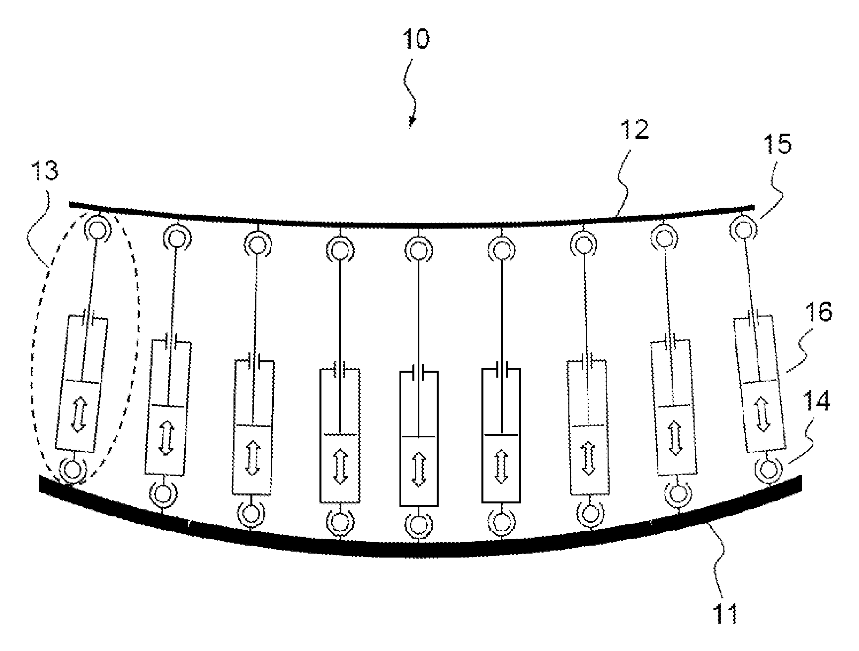
Examples
first embodiment
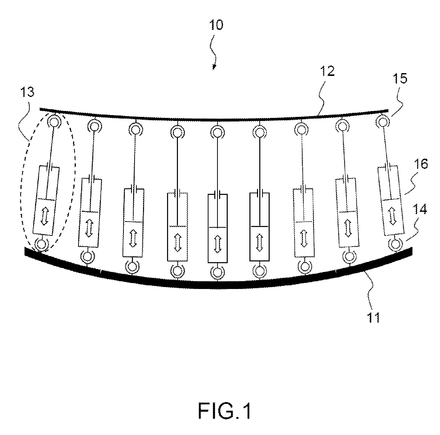
[0028]FIGS. 2.a and 2.b represent one of the coupling means 13 of the antenna reflector 10 according to the invention, in a storage configuration in FIG. 2.a, and in an operational configuration in FIG. 2.b.
[0029]Storage configuration, often also called stacking configuration, refers to the configuration of a satellite platform and of its equipment that makes it possible to hold all the equipment stationary against the platform, in particular during a launch phase using a launcher spacecraft. In the operational configuration, often also called the unstacked configuration, the equipment is released and positioned so as to allow it to operate and participate in the satellite's missions.
[0030]The axis of translation of the linear actuator 16 is labelled X1 in FIGS. 2.a and 2.b. The linear actuator 16 of each of the coupling means 13 comprises a rotary motor 20 and a screw 21-nut 22 assembly, which are connected to the two links of finger ball joint type 14 and 15, and able to generate...
second embodiment
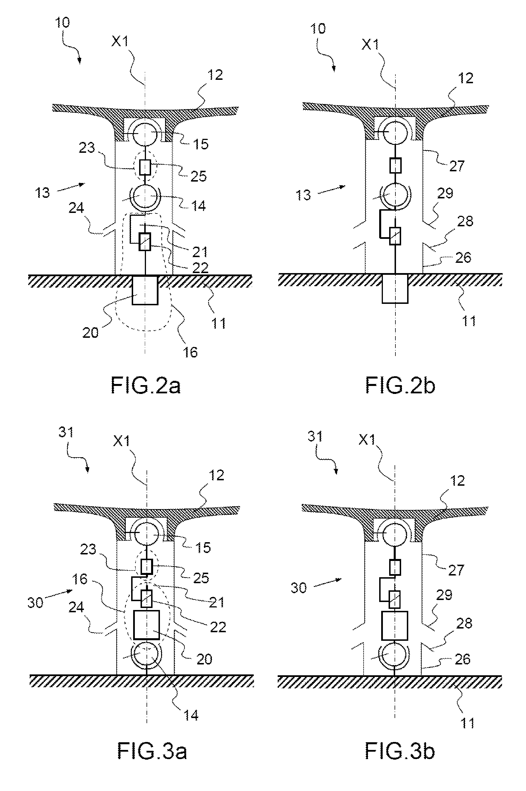
[0050]FIGS. 3.a and 3.b represent a means of coupling 30 of an antenna reflector 31 according to the invention, in a storage configuration (3.a) and in an operational configuration (3.b).
[0051]The antenna reflector 31 comprises the rigid support 11, the membrane 12 and coupling means 30. The coupling means 30 comprise the same components as the coupling means 13, which will bear the same names for convenience.
[0052]In this second embodiment, each of the coupling means 30 comprises several components connected together, and positioned in series between the rigid structure 11 and the membrane 12 in the following order:[0053]the first link of finger ball joint type 14, fixed on the rigid structure 11,[0054]the rotary motor 20,[0055]the screw 21 cooperating with the nut 22,[0056]the rod 23,[0057]the second link of finger ball joint type 15, fixed on the membrane 12.
[0058]Advantageously, the rotary motor 20 and the screw 21-nut 22 assembly are positioned between the two links of finger b...
PUM
 Abstract
Description
Claims
Application Information