Foam generating apparatus and method for compressed air foam systems

a technology which is applied in the field of foam generating apparatus and compressed air foam system, can solve the problems of low foam quality, low foam quality, and the cost of retrofitting existing water-based systems to oafs equipmen

Active Publication Date: 2016-06-21
ROWE CARROLL G
View PDF5 Cites 1 Cited by
  • Summary
  • Abstract
  • Description
  • Claims
  • Application Information

AI Technical Summary

Benefits of technology

[0006]The present invention is a OAFS foam generator that is particularly suited for retrofit OAFS applications and which does not significantly restrict the flow of liquid through the system when operated in a non-OAFS mode.

Problems solved by technology

CAFS may be particularly valuable for rural fire departments, because the use of foam reduces the amount of water required to extinguish a fire, and rural departments are often quite limited in the amount of water that they have available at any particular fire.
A challenge with CAFS design is the maintenance of a correct balance between incoming water and air pressure.
If these pressures are not correctly balanced, a low-quality foam, or even no foam at all, may result.
One problem raised by the widespread adoption of OAFS is the cost of retrofitting existing water-based systems to employ OAFS equipment.
Since rural fire departments are generally not as well funded as many urban fire departments, the replacement of an existing, fully functional water-based pumper truck with one featuring an integrated OAFS unit is often cost prohibitive.
A problem arises, however, in that the OAFS equipment may not fit neatly within the available space on an existing pumper truck, which complicates the retrofit process and increases the associated cost.
Another problem raised by the adoption of OAFS systems is that there may be certain applications where, even though a OAFS system is available, it is desirable to use only water in fighting a particular fire.

Method used


Image

  • Foam generating apparatus and method for compressed air foam systems
  • Foam generating apparatus and method for compressed air foam systems
  • Foam generating apparatus and method for compressed air foam systems

Examples


Embodiment Construction

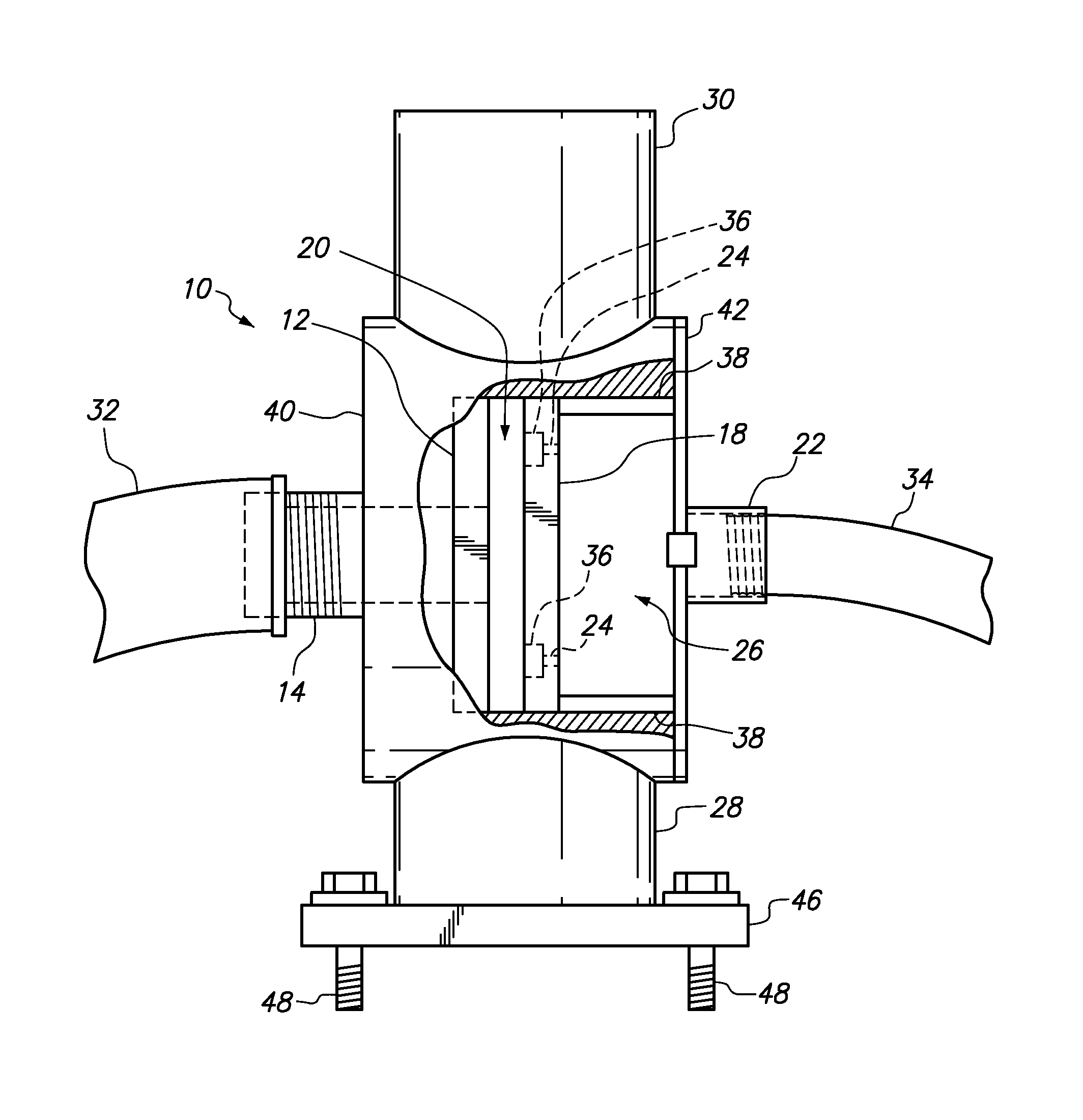
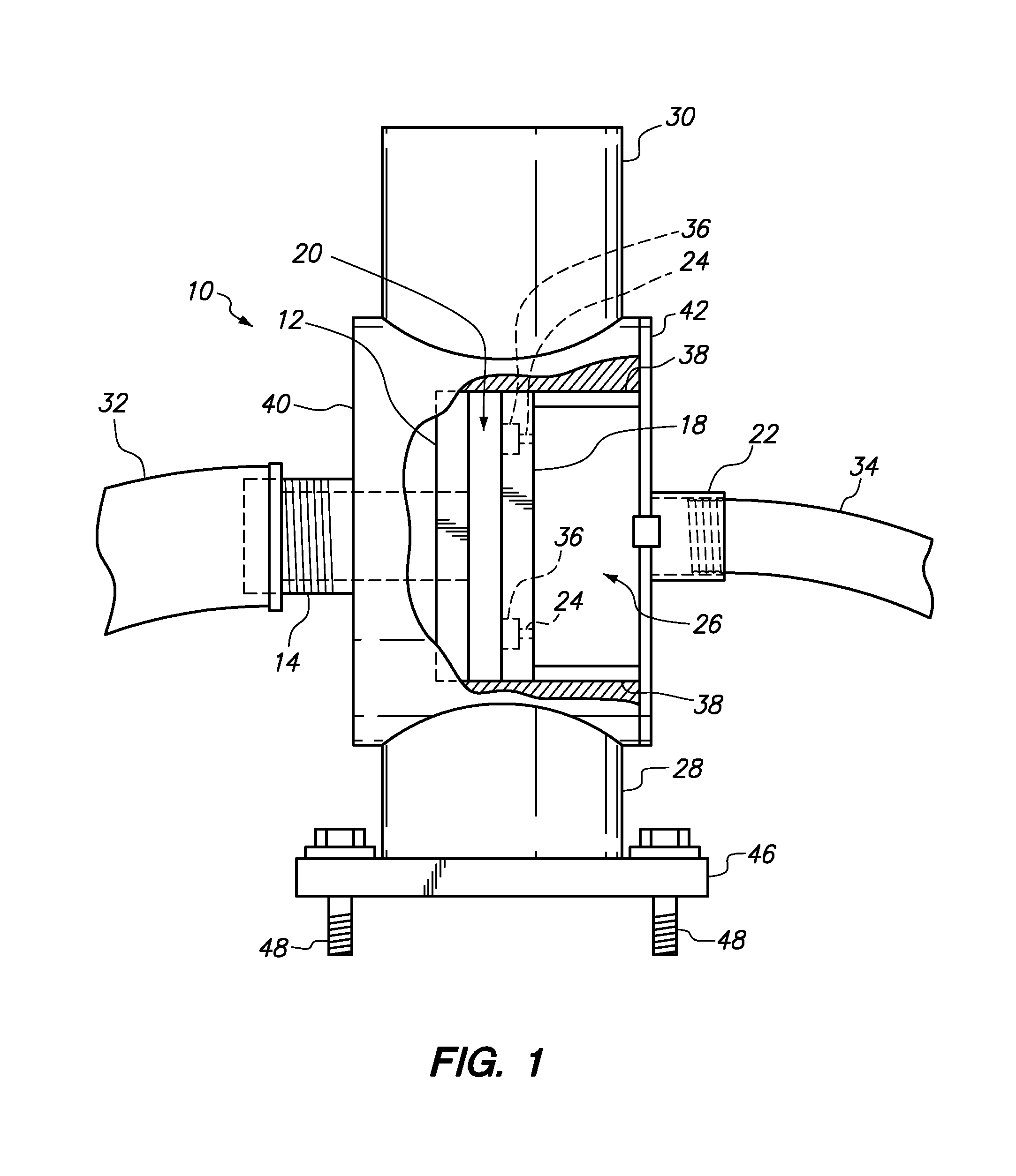
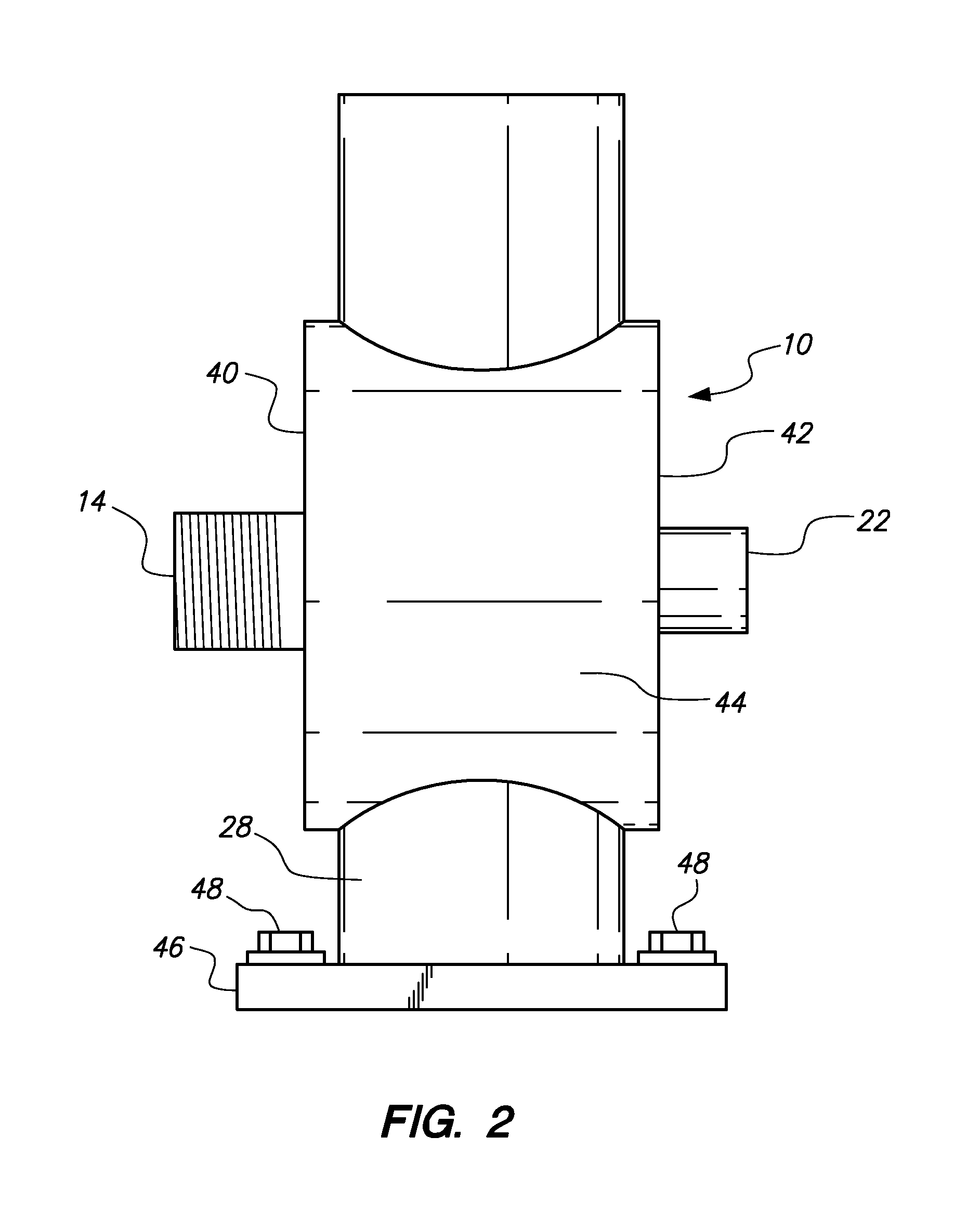
[0013]The preferred embodiment of the present invention may now be described with reference to FIGS. 1 and 2. A mixing chamber 10 serves as the location where the mixing of solution and air takes place in order to produce CAFS foam. Chamber 10 is preferably mounted on a firefighting vehicle, although the invention is not so limited. Chamber 10 is of a generally cylindrical shape, having a circular first end 40, a circular second end 42, and an annular sidewall 44. Each of circular first end 40, circular second end 42, and annular sidewall 44 may collectively be referred to as the “chamber wall” herein. Chamber 10 is preferably formed entirely of a strong, rust-resistant metal alloy, such as stainless steel, although brass and other materials may be substituted in alternative embodiments.

[0014]Solution inlet 14 passes through first end 40 of chamber 10, and allows for the introduction of solution into chamber 10. The solution is fed to solution inlet 14 through solution hose 32. Outs...


PUM


Abstract

An apparatus for generating foam for use in a compressed air foam system (CAFS) incorporates two plates housed in a chamber. A surfactant solution enters the chamber through an orifice in one plate. Pressurized air enters the chamber through a number of channels bored through the other plate, the channels appearing in an annular groove which circumscribes the solution inlet. The restricted area between the plates balances the pressure between the incoming solution and air by achieving an equilibrium at some particular radius out from the center of the two plates. A liquid, such as water or a surfactant and water solution, may optionally be introduced through an inlet into the chamber. The resulting mixture is fed through a main outlet positioned along the chamber wall.

Description

BACKGROUND OF THE INVENTION[0001]Various compressed air foam systems (CAFS) have been used in firefighting for quite some time. The original CAFS developments were made by the U.S. Navy during the 1940's as a method to fight fires on ships. In its most basic form, a CAFS is simply a means for mixing air and water with a surfactant in order to produce a water-based foam that is used to extinguish fires. CAFS provides quicker “knockdown” against potent fires, deeper penetration of fuels, and gives firefighters the advantage of making their initial attack against a fire from a significantly greater distance than with a traditional water stream or fog pattern. The bubble structure allows for greater expansion of delivered water surface area, allowing for greater heat reduction compared to equal amounts of plain water. Foam blankets allow for pre-treatment of fuels that are not already involved in the fire, and have less adverse impact on property, as well as helping to prevent damage to...

Claims


Application Information

Patent Timeline
Patent Type & Authority Patents(United States)
IPC IPC(8): A62C2/00A62C5/02A62C3/06
CPCA62C5/022A62C5/02A62C3/06
Inventor ROWE, CARROLL G.
Owner ROWE CARROLL G
Why Eureka
Try Eureka