
Adjustable doweling jig

a doweling jig and adjustment technology, applied in the field of woodworking tools, can solve the problems of limited use of doweling jigs, noticeable and undesirable edges at the joint formed by the boards, and achieve the effect of reducing labor costs and the time required to manufacture the holes, and reducing or minimizing the mismatch of mating doweling holes

Active Publication Date: 2016-06-21
NOMIS LLC
View PDF18 Cites 10 Cited by
  • Summary
  • Abstract
  • Description
  • Claims
  • Application Information

AI Technical Summary

Benefits of technology

[0008]In view of the above, embodiments of the present invention provide an adjustable doweling jig that overcomes existing problems in the art. More particularly, embodiments of the present invention provide a new and improved adjustable doweling jig having a plurality of bore guides that are adjustable relative to a base so that the jig is not limited to a predefined number of bore guide locations. Still more particularly, embodiments of the present invention provide an adjustable doweling jig that has a plurality of bore guides that are simultaneously positionable relative to multiple boards using a single control, thereby reducing labor costs and the time required to manufacture the holes. Still more particularly, embodiments of the present invention provide an adjustable doweling jig that reduces or minimizes mating doweling hole mismatch by allowing a user to manufacture multiple doweling holes in multiple boards in a single fixturing operation.

Problems solved by technology

Unfortunately, contemporary doweling jigs present several drawbacks.
As a result, contemporary doweling jigs are limited to forming dowel holes at a number of predefined locations as measured from a reference point of the jig, regardless of the dimensions of the workpiece operated upon.
Unfortunately, because of this refixturing, there is a risk that the resulting dowel holes will not properly match up with the first board's dowel holes, so that there is a noticeable and undesirable edge at the joint formed by the boards.
Such a result is particularly undesirable where a flat surface between mating boards is desired, such as in table tops or other similar designs.

Method used


Image

  • Adjustable doweling jig
  • Adjustable doweling jig
  • Adjustable doweling jig

Examples


Embodiment Construction

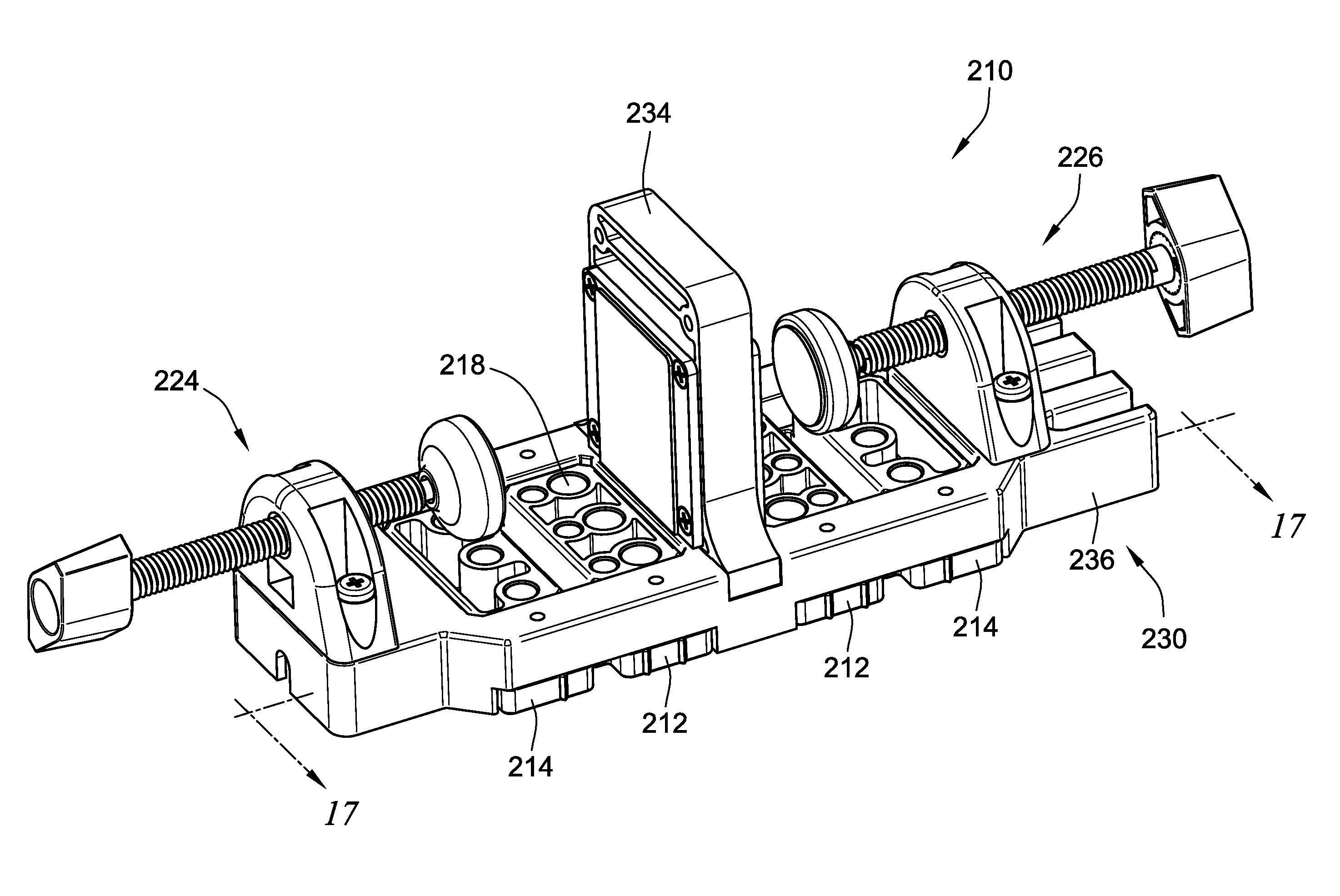
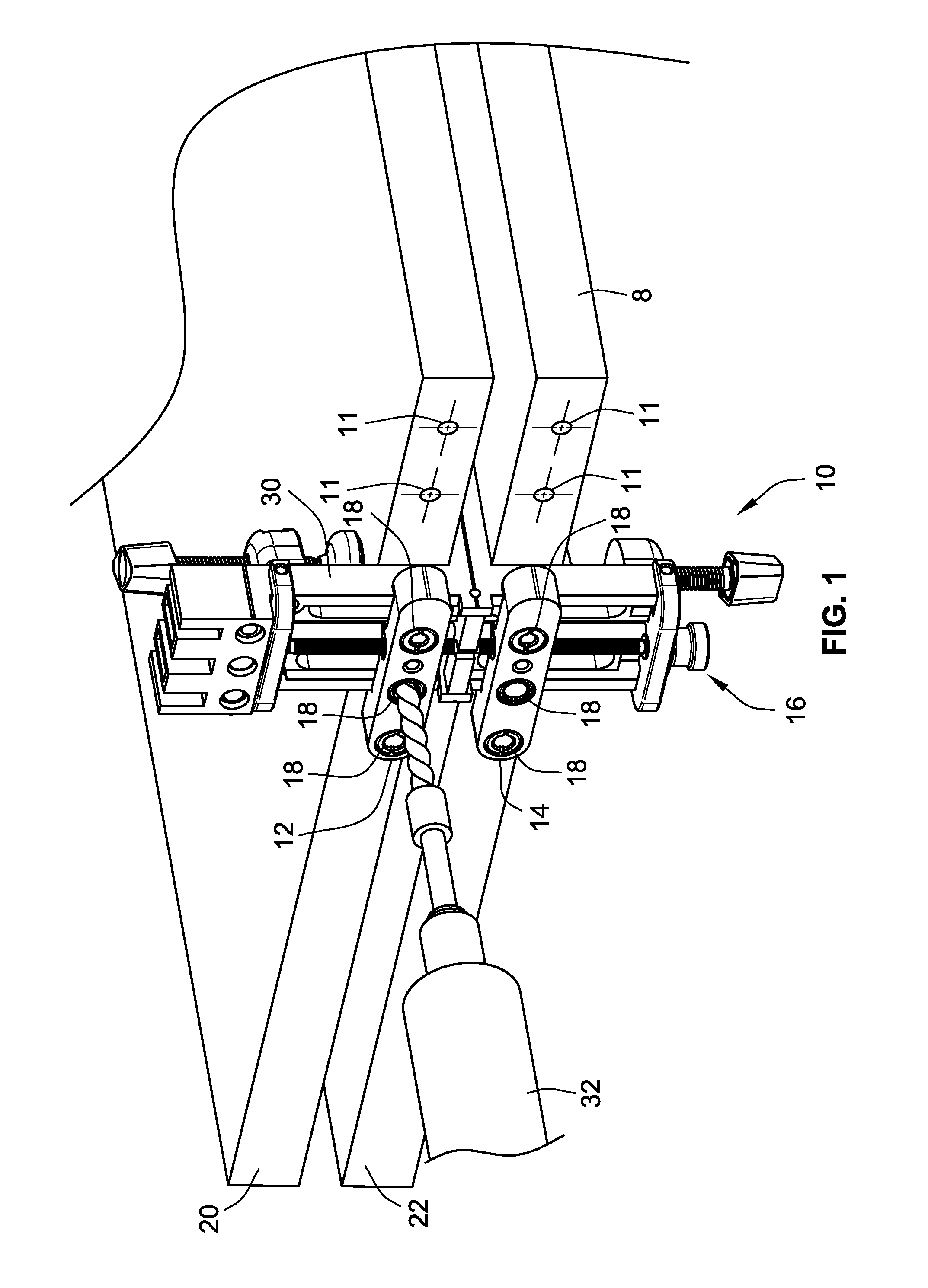
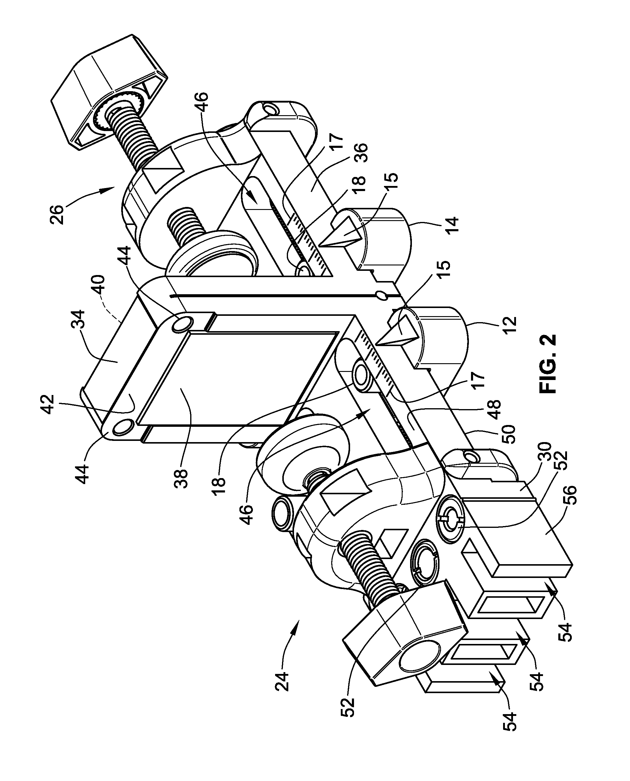
[0062]Turning now to the drawings, an adjustable doweling jig 10 mounted to a work table 8 is illustrated in FIG. 1. The adjustable doweling jig 10 has a pair of adjustable bore guide carriers 12, 14 that are adjustable relative to a base structure 30 of the doweling jig 10. The bore guide carriers 12, 14 are adjustable by way of an adjustment mechanism 16 to thereby position a plurality of bore guides 18 relative to a pair of work pieces 20, 22 clamped to the adjustable doweling jig 10.

[0063]In the illustrated embodiment, the bore guide carriers 12, 14 are identical. However, it is recognized that they may take on different forms, independent of one another, in other embodiments. The bore guides 18 are adjustable to a variety of locations and do not have an otherwise fixed position such as in the prior art devices described above. Once the bore guides 18 are positioned in a desired location, a boring tool 32 can then be used to place the appropriate dowel holes 11 in the workpieces...


PUM

PropertyMeasurementUnit
widthaaaaaaaaaa
distancesaaaaaaaaaa
dimensionsaaaaaaaaaa

Abstract

An adjustable doweling jig is provided. The adjustable doweling jig has a pair of bore guide carriers that are symmetrically and simultaneously adjustable relative to a base structure of the doweling jig. The bore guide carriers carry a plurality of bore guides such that dowel holes can be placed using the bore guides at a broad range of locations, limited only by the size of the jig.

Description

CROSS-REFERENCE TO RELATED PATENT APPLICATIONS[0001]This patent application is a Continuation-in-Part of co-pending U.S. patent application Ser. No. 12 / 813,154, filed Jun. 10, 2010 the entire teachings and disclosure of which are incorporated herein by reference thereto.FIELD OF THE INVENTION[0002]This invention generally relates to tools for woodworking and more specifically to doweling jigs used for placing dowel holes in a workpiece.BACKGROUND OF THE INVENTION[0003]Doweling jigs are used in woodworking to generate dowel holes in a workpiece. The jig has several bore guides arranged at fixed distances relative to a reference point of the jig. The bore guides generally have open bores that allow a boring tool such as a drill to pass through a portion of the jig and drill dowel holes in the workpiece. The holes receive dowels used to join workpieces together. Once a dowel hole is drilled, a portion of a dowel is inserted into the dowel hole, leaving a portion of the dowel exposed. T...

Claims


Application Information

Patent Timeline
Patent Type & Authority Patents(United States)
IPC IPC(8): B23B47/28
CPCB23B47/288B23B2247/12Y10T29/49826Y10T408/567
Inventor ADKINS, EDWARD D.KARKOSCH, JOEWATERMANN, DAVID R.
Owner NOMIS LLC
Learn More