Connector

a technology of connecting rods and connectors, applied in the direction of coupling devices, two-part coupling devices, electrical apparatus, etc., can solve problems such as presenting a decrease in impedance, and achieve the effect of suppressing crosstalk and suppressing the decrease in impedan

Active Publication Date: 2016-06-28
HOSIDEN CORP
View PDF10 Cites 51 Cited by
  • Summary
  • Abstract
  • Description
  • Claims
  • Application Information

AI Technical Summary

Benefits of technology

[0006]By a connector of the present invention, it is possible to suppress crosstalk and suppress decrease in impedance.

Problems solved by technology

In the case of using a connector with a metal plate intervened between contact rows as in Patent Literature 1, as a connector for high-speed signal transmission, decrease in impedance presents a problem.

Method used


Image

  • Connector
  • Connector
  • Connector

Examples


Embodiment Construction

[0013]An embodiment of the present invention will be described below in detail. Components having the same function will be given the same reference numeral, and redundant description will be omitted.

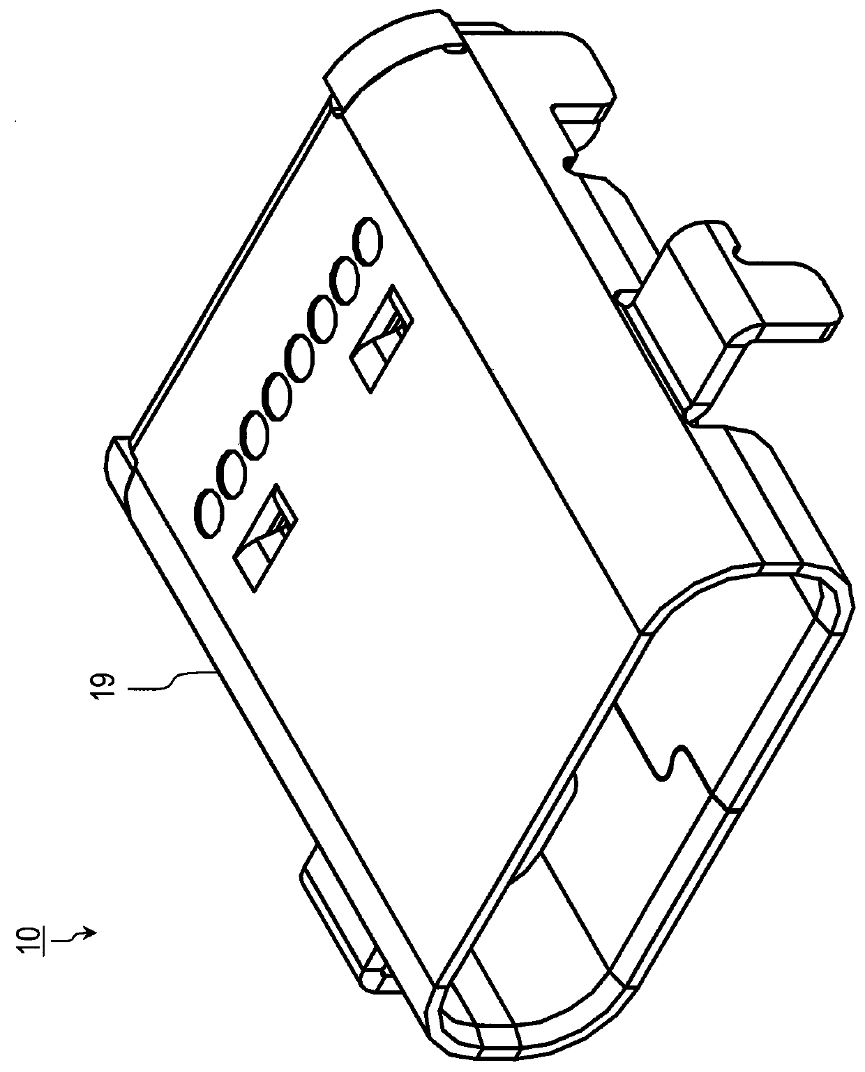
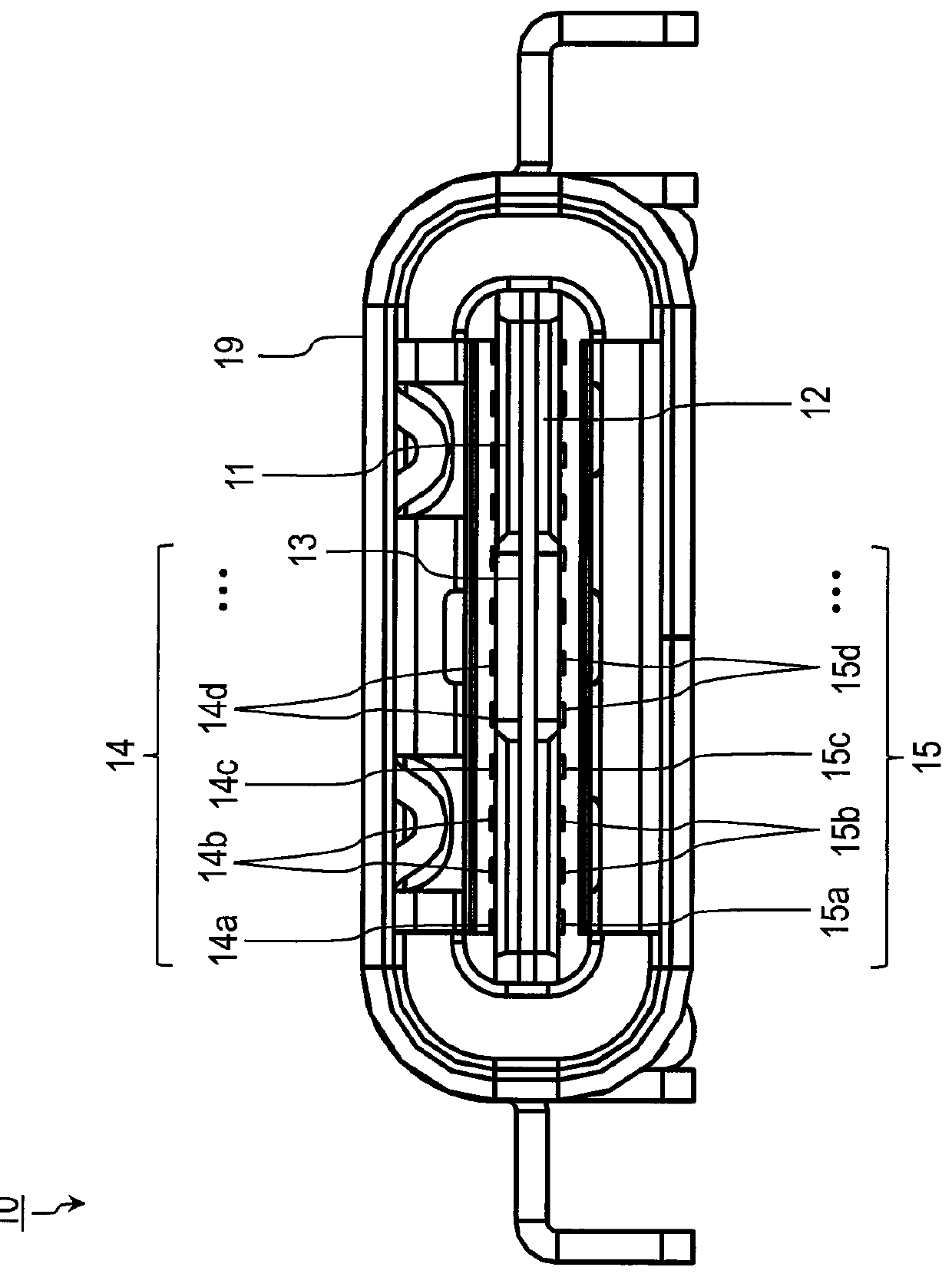
[0014]A connector of the embodiment of the present invention will be described below with reference to FIGS. 1 and 2. FIG. 1 is a perspective view (on a plane side) showing a connector 10 of the present embodiment. FIG. 2 is a front view showing the connector 10 of the present embodiment. As shown in FIG. 1, the connector 10 of the present embodiment is provided with a case 19 covering the internal structure of the connector 10, with one end thereof open. A counterpart connector is inserted from the open end of the case 19, so that the counterpart connector and the connector 10 are connected and electrically connected. The case 19 is formed, for example, with metal. As shown in FIG. 2, there are provided inside the case 19: a first insulator substrate 11; a first contact 14 configured b...


PUM


Abstract

A connector comprising: a first insulator substrate; a first contact configured by arranging a plurality of contact pins including contact pins for differential signals as an array, on a top surface of the first insulator substrate; a second insulator substrate; a second contact configured by arranging a plurality of contact pins including contact pins for differential signals as an array in the same direction as the array direction of the first contact, on an undersurface of the second insulator substrate; and a metal plate sandwiched by an undersurface of the first insulator substrate and a top surface of the second insulator substrate; and one or more holes are formed in an area on the metal plate, the area being sandwiched by the contact pins for differential signals of the first and second contacts facing each other.

Description

TECHNICAL FIELD[0001]The present invention relates to a connector for high-speed signal transmission.BACKGROUND ART[0002]In a conventional connector provided with a plurality of rows of contact pins (contacts), the size of the connector is sufficiently large. Therefore, in many cases, a distance between rows of contacts is sufficiently long, and differential signal contacts do not exist at overlapping positions. Thus, crosstalk among the contacts does not matter much. On the other hand, even if crosstalk among the contacts presents a problem, it is possible to suppress the crosstalk by causing a metal plate to intervene between contact rows (see Japanese Patent Application Laid-Open No. 06-325826, which will be hereinafter referred to as “Patent Literature 1”).[0003]In the case of using the connector of Patent Literature 1 as a connector for low-speed signal transmission, decrease in impedance caused by causing the metal plate to intervene does not matter. In the case of using a con...

Claims


Application Information

Patent Timeline
Patent Type & Authority Patents(United States)
IPC IPC(8): H01R24/00H01R24/60H01R107/00
CPCH01R24/60H01R2107/00H01R12/724H01R13/6582
Inventor MIYOSHI, TOSHIHARUKONDO, HAYATO
Owner HOSIDEN CORP
Why Eureka
Try Eureka