Rider controlled zip line trolley brake system

a brake system and rider technology, applied in the direction of rope railways, friction linings, building rescue, etc., can solve the problems of smallwood devices that are not intended or practical for use on modern zip line systems, devices that cannot be used to achieve speed-retarding features on a common zip line system, and devices that cannot be used to achieve the effect of speed-retarding

Inactive Publication Date: 2016-07-05
BRANNAN KENTON M
View PDF25 Cites 14 Cited by
  • Summary
  • Abstract
  • Description
  • Claims
  • Application Information

AI Technical Summary

Benefits of technology

[0029]In accordance with one embodiment, a zip line trolley is provided which affords a rider control of his or her speed while traversing along a suspended cable. As the rider descends along the suspended cable, he or she gently squeezes either or both of a pair of handbrakes. As a result, a dynamic frictional force is applied to the suspended cable which slows and ultimately brings the rider to a gentle stop at a precise location. Upon reaching a complete stop, riders can quickly and easily remove the trolley from the suspended cable and transport it to another.

Problems solved by technology

This is contrary to the rider controlled zip line trolley brake system which applies frictional forces to the suspended cable.
Smallwood's device is not intended, or practical for use on a modern zip line system.
This device would not operate as intended if used in conjunction with a metallic suspended cable rather than a rope.
Thus, this speed-retarding feature cannot be realized on a common zip line system.

Method used


Image

  • Rider controlled zip line trolley brake system
  • Rider controlled zip line trolley brake system
  • Rider controlled zip line trolley brake system

Examples


Embodiment Construction

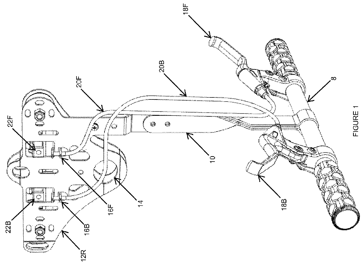
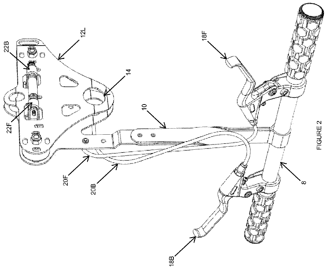
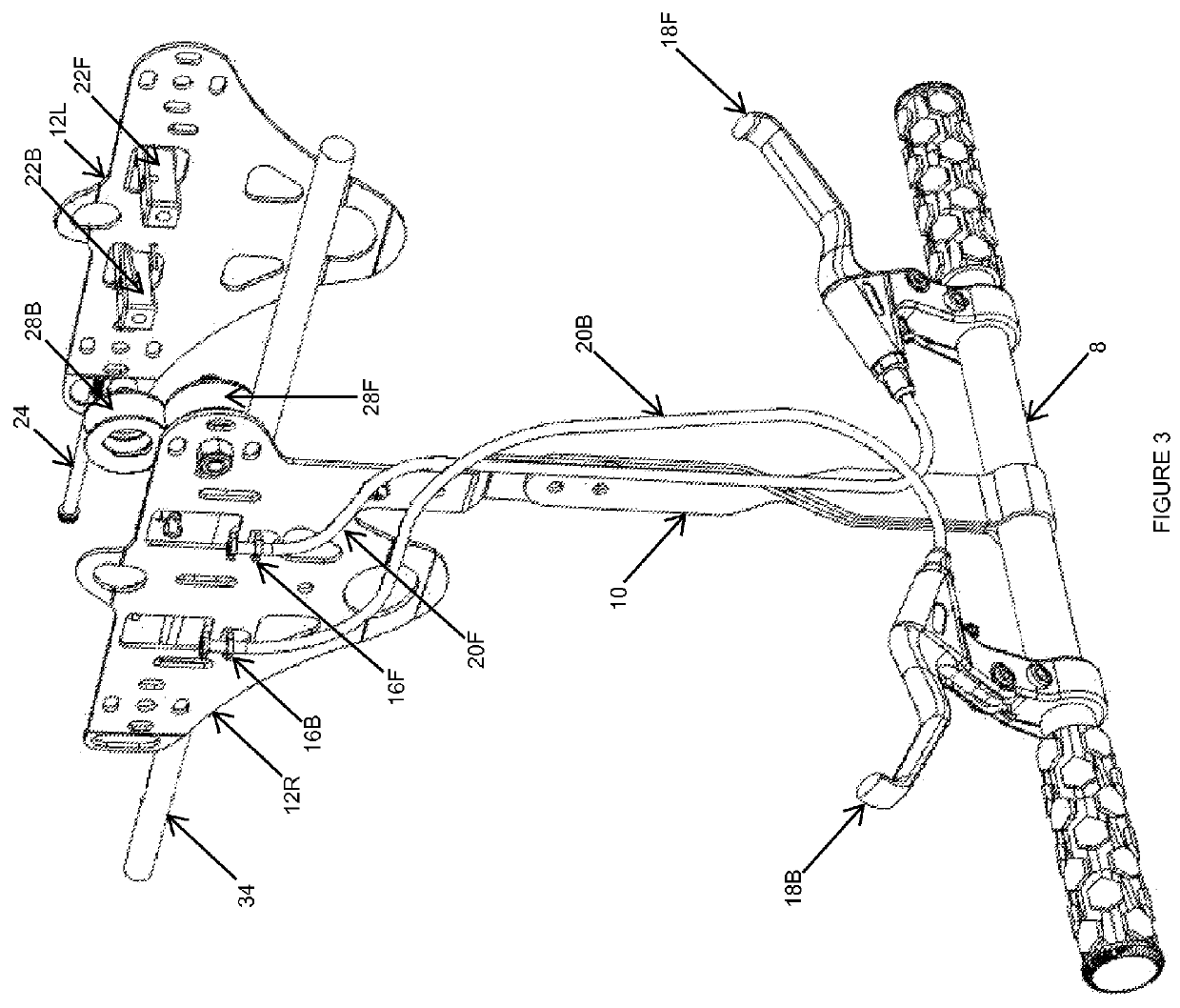
[0055]The trolley and associated braking mechanism will now be described with reference to the accompanying drawing figures. It is to be understood that the drawing FIGS. 1, 2, 3 and 4 are meant to be only illustrative, that they are not necessarily drawn to scale, and that some details, which would be obvious to those of ordinary skill in the art, may have been omitted in the interest of simplification and brevity.

[0056]FIGS. 1 and 2 illustrate a complete view of the rider controlled zip line trolley brake system. The trolley comprises a handle bar 8 and handle mounting bracket 10. The handle mounting bracket 10 is fastened to trolley right plate 12R via common nuts and bolts. Trolley left plate 12L is similar and opposite to trolley right plate 12R, less a connecting means for a handle. A harness connection 14 is used to secure riders via a conventional harness or similar safety device (not shown). Back cable sleeve mounting bracket 16B and front cable sleeve mounting bracket 16F ...


PUM


Abstract

An improved zip line trolley allowing a rider control of his or her speed while traversing along a suspended cable. The trolley comprises front and back wheels conjoined via left and right trolley plates and a handle bar. Front and back hand brake levers are mounted onto the handle bar. When front and back hand brake levers are squeezed by the rider, they create a constricting force which applies friction to the suspended cable via brake pads. This frictional force slows the rider's speed to his or her desired rate and brings the rider to a safe stop at a precise location along the suspended cable. The rider is able to quickly and easily remove the trolley from the suspended cable and transport it to another.

Description

CROSS-REFERENCE TO RELATED APPLICATIONS[0001]This application claims the benefit of provisional patent application Ser. No. 61 / 773,170 filed 2013 Mar. 6 by the present inventor.FEDERALLY SPONSORED RESEARCH[0002]Not ApplicableREFERENCE TO SEQUENCE LISTING[0003]Not ApplicableBACKGROUND[0004]1. Field[0005]This application relates to suspended cable transport systems commonly known as zip lines. More specifically, this application relates to trolleys for zip line or other suspended cable systems which allow riders to maintain control of their speed of descent while traversing along a suspended cable.[0006]2. Prior Art[0007]Common zip lines are thrill-ride systems predominantly utilized in applications for amusement. A common zip line system includes a suspended cable (constructed of aluminum, steel or similar metallic material) stretched between, and rigidly affixed to, separate supporting structures. One end of the suspended cable is affixed to a support structure which is located at a...

Claims


Application Information

Patent Timeline
Patent Type & Authority Patents(United States)
IPC IPC(8): A63G9/16A62B1/14F16D69/02B61B7/00B61H9/02
CPCB61H9/02A62B1/14B61B7/00F16D69/02
Inventor BRANNAN, KENTON MICHAEL
Owner BRANNAN KENTON M
Why Eureka
Try Eureka