Color display device

a display device and color technology, applied in static indicating devices, instruments, non-linear optics, etc., can solve the problems of inacceptable choice of display devices, dim white state,

Active Publication Date: 2016-07-05
E INK CORPORATION
View PDF88 Cites 81 Cited by
  • Summary
  • Abstract
  • Description
  • Claims
  • Application Information

AI Technical Summary

Problems solved by technology

The disadvantage of such a technique is that the white state is fairly dim.
Even with this approach, the white level is normally still substantially less than half of that of a black and white display, rendering it an unacceptable choice for display devices, such as e-readers or displays that need well readable black-white brightness and contrast.

Method used


Image

  • Color display device
  • Color display device
  • Color display device

Examples


example 1

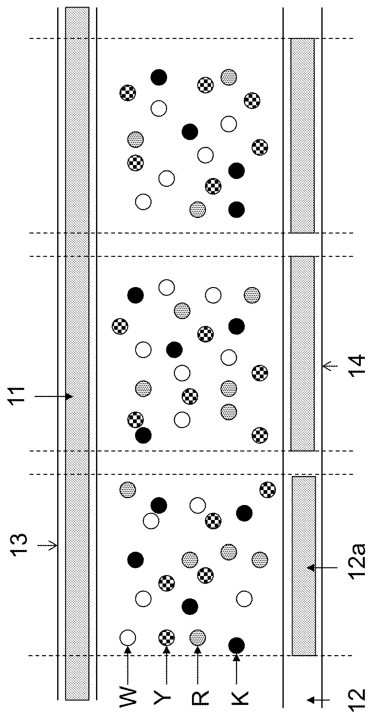
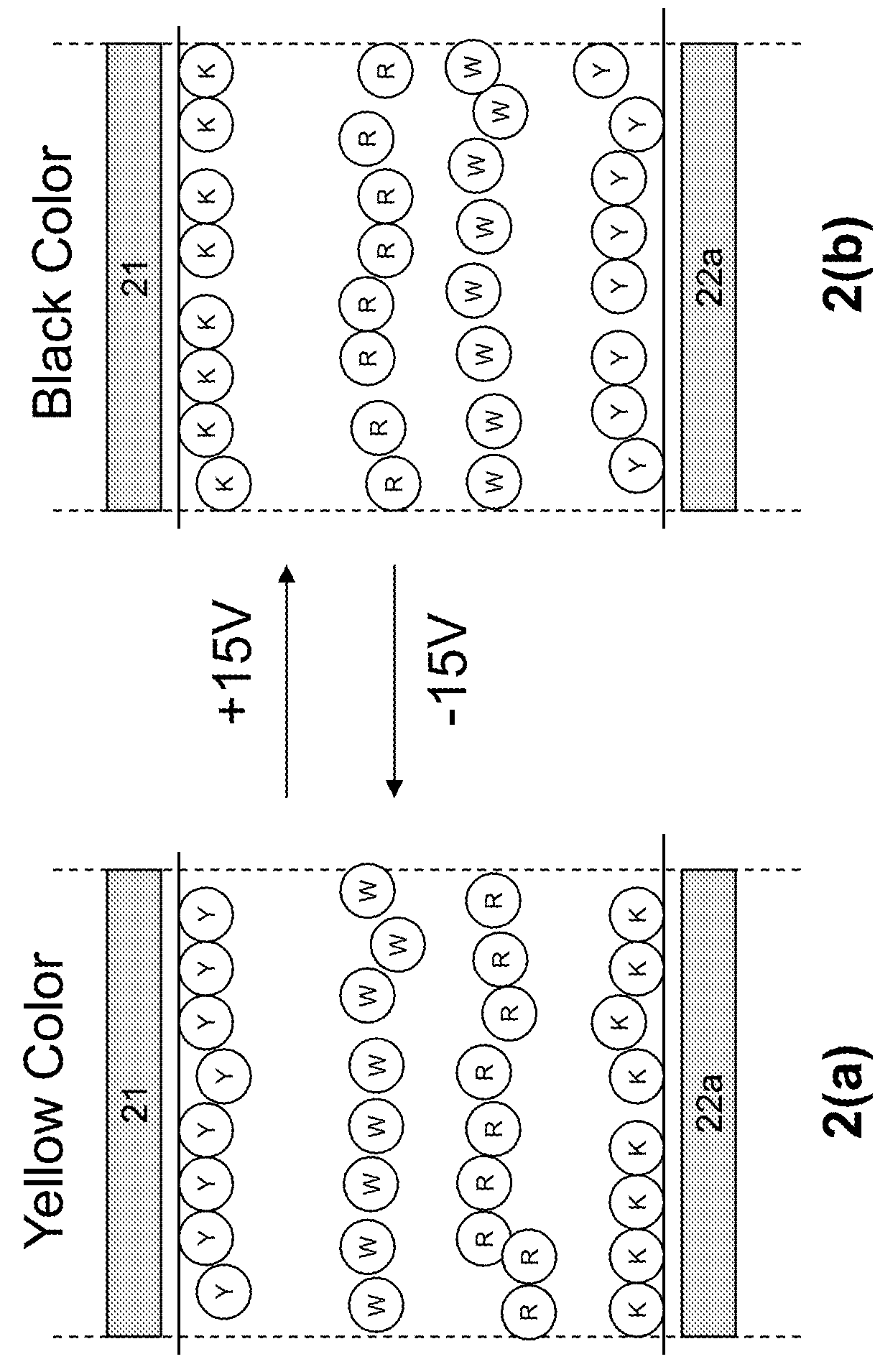
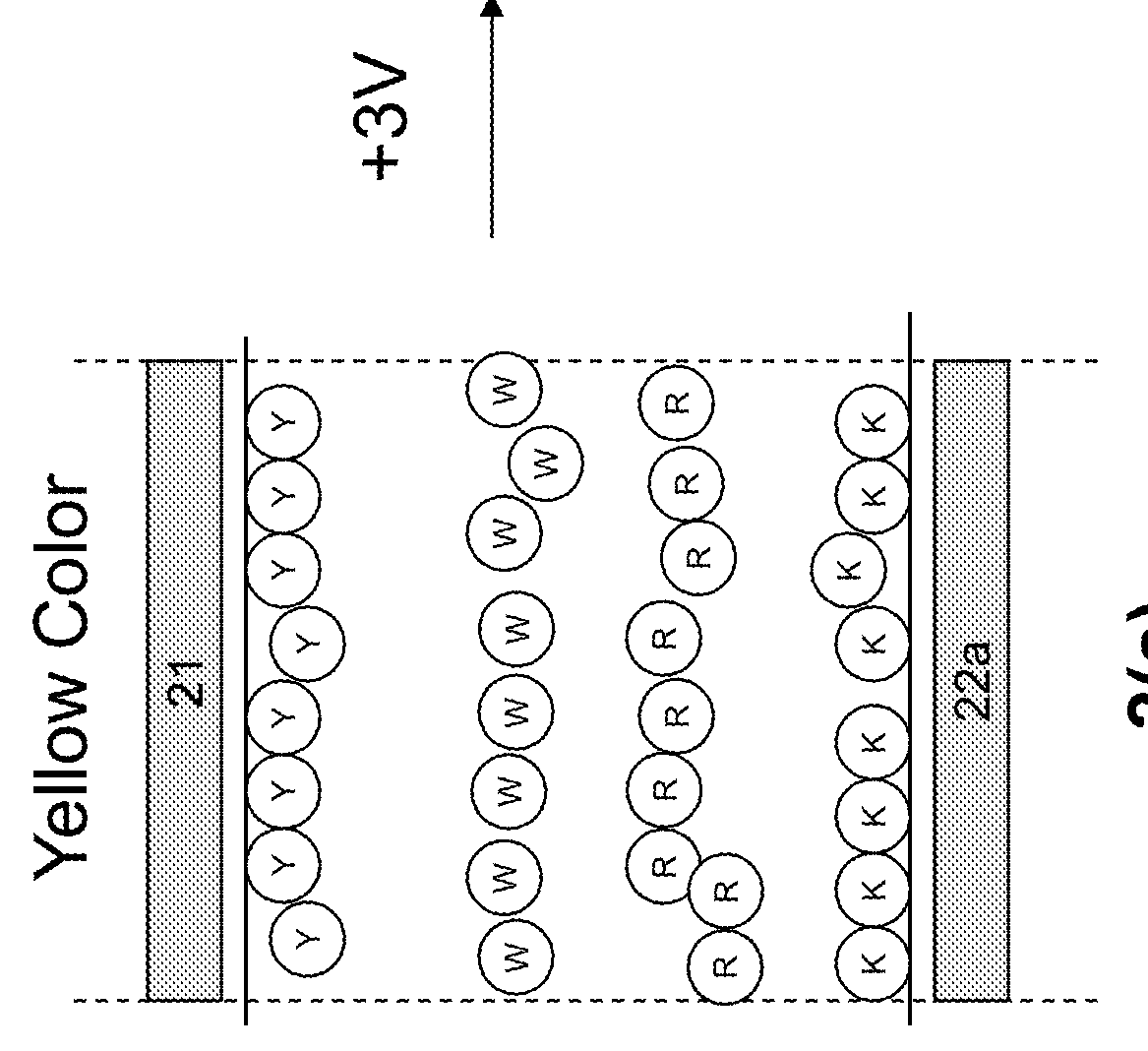
[0057]This example is demonstrated in FIG. 2. The high positive particles are of the black color (K); the high negative particles are of a yellow color (Y); the low positive particles are of a red color (R); and the low negative particles are of a white color (W).

[0058]In FIG. 2(a), when a high negative voltage potential difference (e.g., −15V) is applied to a pixel for a time period of sufficient length, an electric field is generated to cause the yellow particles (Y) to be pushed to the common electrode (21) side and the black particles (K) pulled to the pixel electrode (22a) side. The red (R) and white (W) particles, because they carry weaker charges, move slower than the higher charged black and yellow particles and as a result, they stay in the middle of the pixel, with white particles above the red particles. In this case, a yellow color is seen at the viewing side.

[0059]In FIG. 2(b), when a high positive voltage potential difference (e.g., +15V) is applied to the pixel for a ...


PUM

PropertyMeasurementUnit
dielectric constantaaaaaaaaaa
sizeaaaaaaaaaa

Abstract

The present invention provides a color display device in which each pixel or sub-pixel can display four high quality color states. More specifically, an electrophoretic fluid is provided which comprises four types of particles, dispersed in a solvent or solvent mixture. The fluid may further comprise substantially uncharged neutral buoyancy particles.

Description

[0001]This is a continuation-in-part application of U.S. application Ser. No. 14 / 279,173, filed May 15, 2014; which claims the benefit of U.S. Provisional Application Nos. 61 / 824,887, filed May 17, 2013; 61 / 893,831, filed Oct. 21, 2013; and 61 / 974,858, filed Apr. 3, 2014. The contents of the above-identified applications are incorporated herein by reference in their entirety.FIELD OF THE INVENTION[0002]The present invention is directed to a color display device in which each pixel or sub-pixel can display four high quality color states, an electrophoretic fluid for such an electrophoretic display and driving methods for such a display device.BACKGROUND OF THE INVENTION[0003]In order to achieve a color display, color filters are often used. The most common approach is to add color filters on top of three black / white sub-pixels of a pixellated display to display the red, green and blue colors. When a red color is desired, the green and blue sub-pixels are turned to the black state so ...

Claims


Application Information

Patent Timeline
Patent Type & Authority Patents(United States)
IPC IPC(8): G02F1/167G02F1/133G02F1/1333G02F1/1685G02F1/1676G02F1/16762G02F1/1681
CPCG02F1/167G02F1/13306G02F1/133348G02F2001/1676G02F2001/1678G02F2203/34G02F2001/1672G02F1/1676G02F1/1681G02F1/16762G02F1/1685G09G3/2003G09G3/344
Inventor LIN, CRAIGDU, HUIWANG, MING
Owner E INK CORPORATION
Why Eureka
Try Eureka