Ice making machine evaporator with joined partition intersections

a technology of ice making machine and junction, which is applied in the direction of ice production, lighting and heating apparatus, domestic applications, etc., can solve the problems of damage to the criss-cross assembly, non-uniform cube size, and impaired harvest cycle of the ice making machin

Inactive Publication Date: 2016-07-12
PENTAIR FLOW SERVICES
View PDF9 Cites 12 Cited by
  • Summary
  • Abstract
  • Description
  • Claims
  • Application Information

AI Technical Summary

Benefits of technology

[0010]Thus, it is an object of the present disclosure to provide a design of partitions that allows for more complete coating of plating material thereto.
[0011]It is also an object of the present disclosure to provide a design of a partition-evaporator pan assembly that likewise allows for more complete coating of plating material thereto.

Problems solved by technology

However, the slot cross-sectional dimension is not so large that the crossing partition has “wobble” or “play” when inserted; this could result in problems concerning, e.g., the release of the ice slab / cubes during harvest and, due to the fact that water expands during freezing at certain temperatures, the deformation of the relative size of the cells by water freezing in the spacing provided by the “wobble” or “play”, resulting in damage to the crisscross assembly and / or non-uniform cube size.
Without the ability for air to move from cube cell to cube cell behind the slab of ice, the harvest cycle of the ice making machine would be impaired due to a vacuum that would be formed as the slab of ice is pulled away from the evaporator pan by gravity.
Because of the tight or no clearance and potential lack of clearance between the partition surfaces at their intersections, the plating solutions do not always penetrate into the vertical and horizontal partition intersections and provide plating to all the surfaces forming the partition intersections.
This would cause that partition to lean to one side of the slot, leading to an area of tight clearance at the intersection and defeating the purpose of widening the slot.

Method used


Image

  • Ice making machine evaporator with joined partition intersections
  • Ice making machine evaporator with joined partition intersections
  • Ice making machine evaporator with joined partition intersections

Examples


Embodiment Construction

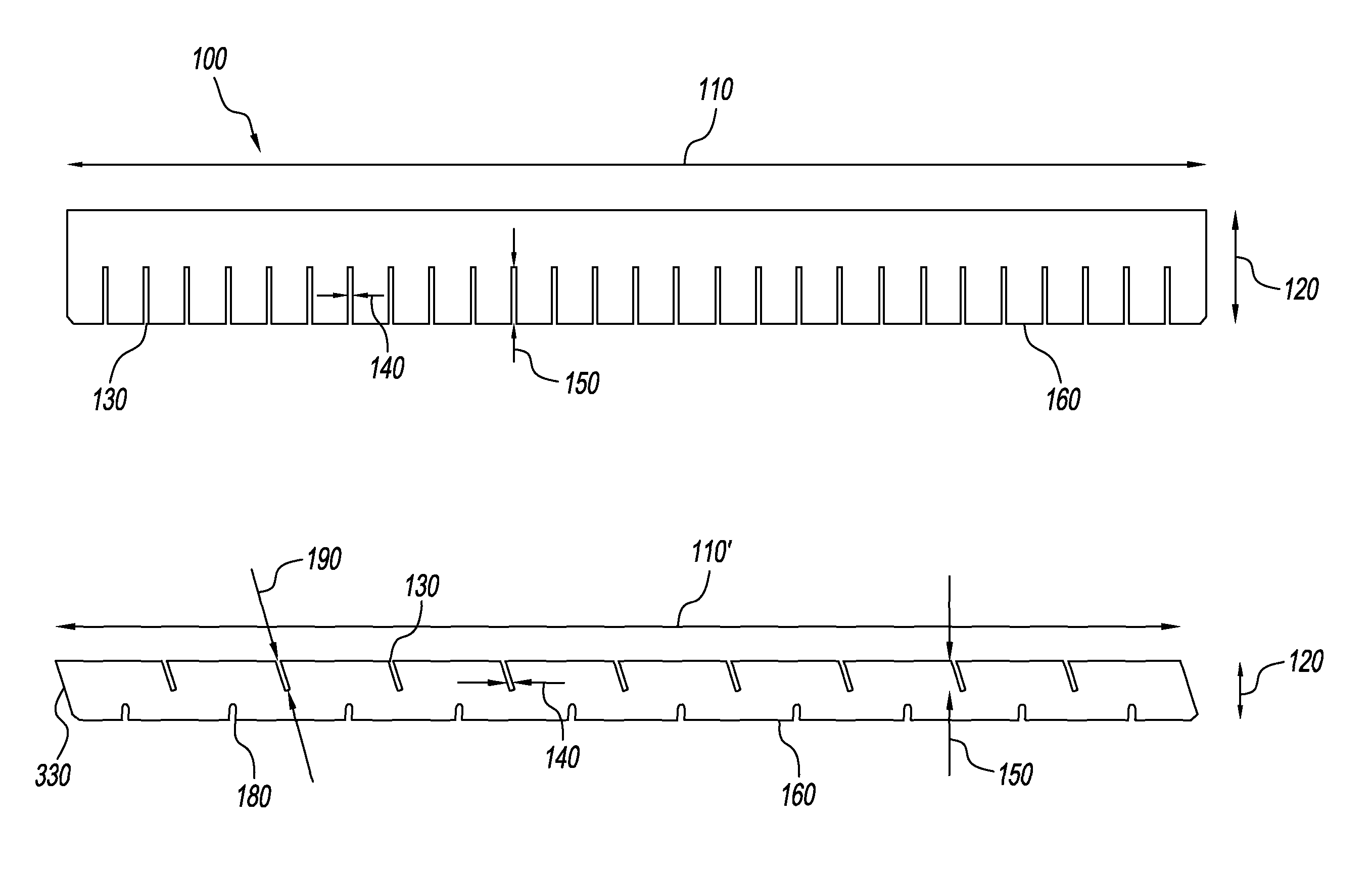
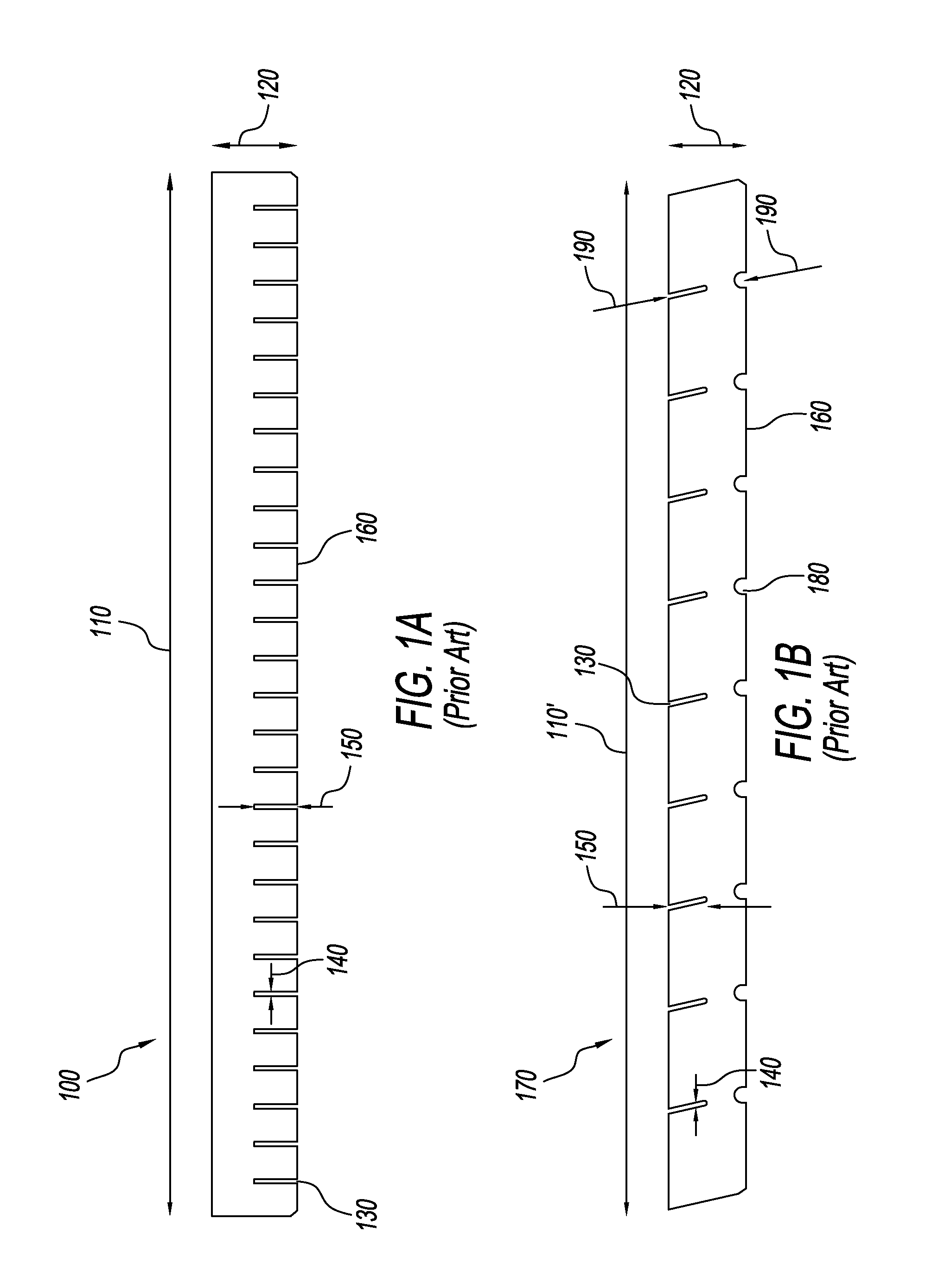
[0033]FIG. 1A shows a side view of a conventional horizontal partition 100. Conventional horizontal partition 100 has a length 110 and a height 120. Conventional horizontal partition 100 has a plurality of substantially equally spaced slots 130, each slot having a width 140 and a depth 150. Length 110 is approximately equal to the inside horizontal surface of a vertically disposed evaporator pan (not shown) to which it is affixed. Height 120 is approximately equal to the depth of a vertically disposed evaporator pan (not shown) to which it is affixed. Slots 130 are substantially equally spaced so as to provide substantially equally sized cells (when mated or joined with a vertical partition) for the formation of ice cubes. Slots 130 are also provided with a depth 150 that is, generally, approximately half the height 120 of horizontal partition 100 and vertical partition 170 (see, FIG. 1B) so that, when inserted into matching slot 130 in vertical partition 170 lower edge 160 of horiz...


PUM

PropertyMeasurementUnit
angleaaaaaaaaaa
angleaaaaaaaaaa
angleaaaaaaaaaa

Abstract

Disclosed are methods and apparatuses for overcoming known plating deficiencies in evaporator assemblies in ice making machine. One embodiment joins the vertical and horizontal partitions together at their intersections so that all surfaces are susceptible for increased soldering / brazing by eliminating the “voids” by changing the location and design of the “weep holes” in the vertical and / or horizontal partitions. This provides more complete capillary path at the joint between the vertical and horizontal partitions and the evaporator pan allowing improved flow via capillary action of solder / brazing alloy during the joining of the assembled vertical and horizontal partition grid to the evaporator pan. Another embodiment increases the clearance between the partitions at their intersections to allow the post-joining plating treatment to penetrate and coat all the partition surfaces by widening the intersection slots in the partitions, but including “stand-off” features to center the mating partition in the widened intersection slot.

Description

CROSS-REFERENCED APPLICATION[0001]This application claims priority to U.S. Provisional Application Ser. No. 61 / 898,175, filed on Oct. 31, 2013, which is incorporated herein in its entirety by reference thereto.BACKGROUND[0002]1. Field of the Disclosure[0003]The present disclosure generally relates to the design of ice making machine evaporator components and the joining process of the evaporator components. In particular, the present disclosure relates to the design and joining of ice making machine evaporator partitions having a crisscross pattern of partitions, and the joining of those partitions to an evaporator pan.[0004]2. Discussion of the Background Art[0005]Conventional ice making machines have an evaporator that is constructed using partitions assembled in a crisscross pattern (generally crisscrossed at about a 90° angle, hereinafter referred to as “horizontal” partitions and / or “vertical” partitions) and joined to an evaporator pan using only butt joints. The crisscross pa...

Claims


Application Information

Patent Timeline
Patent Type & Authority Patents(United States)
IPC IPC(8): B23P15/26F25C1/24
CPCF25C1/246Y10T29/49359
Inventor OLSON, JR., WILLIAM EUGENEWENDT, GERALD WILLIAMHAACK, RAYMOND RANDYISHIOYE, JOHN-PAUL JAMES
Owner PENTAIR FLOW SERVICES
Why Eureka
Try Eureka