Smart illuminated electrical switch with touch control

a technology of intelligent illumination and electrical switches, applied in the direction of instruments, mechanical appliances, optical elements, etc., can solve the problems of difficult to make large uniform illumination features with leds, difficult to effectively convey the operating point of a dimmer switch using light, and indistinct indications, etc., to improve the sensing of the surrounding environment and enhance clarity

Inactive Publication Date: 2016-07-12
OKEEFFE JAMES THOMAS
View PDF13 Cites 92 Cited by
  • Summary
  • Abstract
  • Description
  • Claims
  • Application Information

AI Technical Summary

Benefits of technology

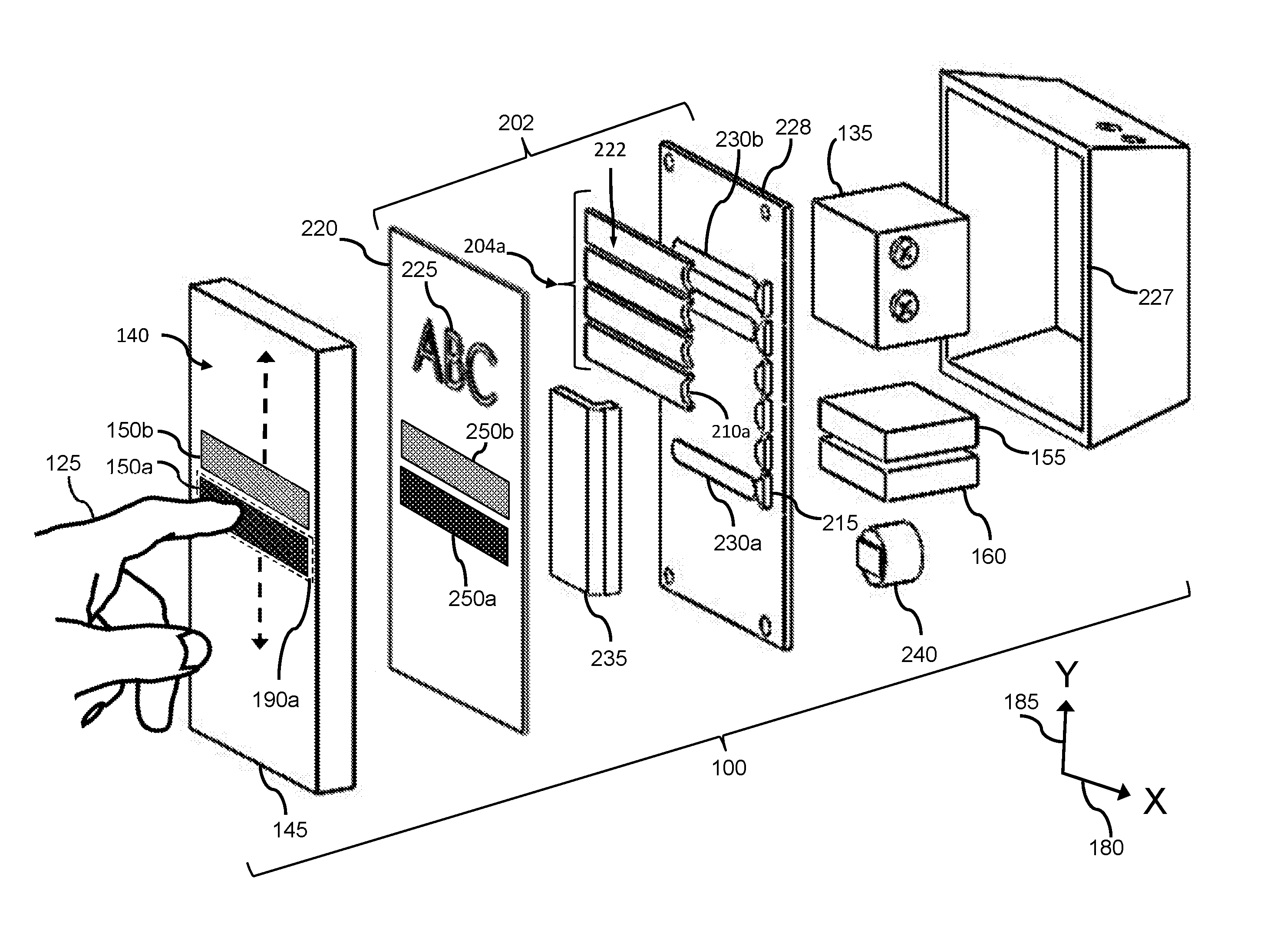
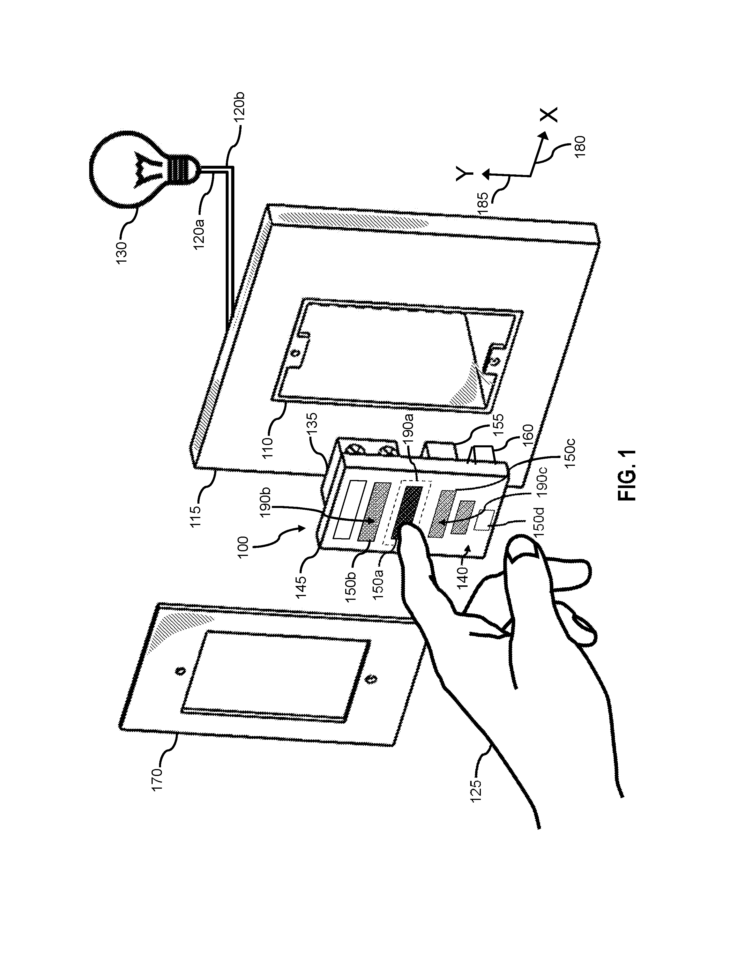
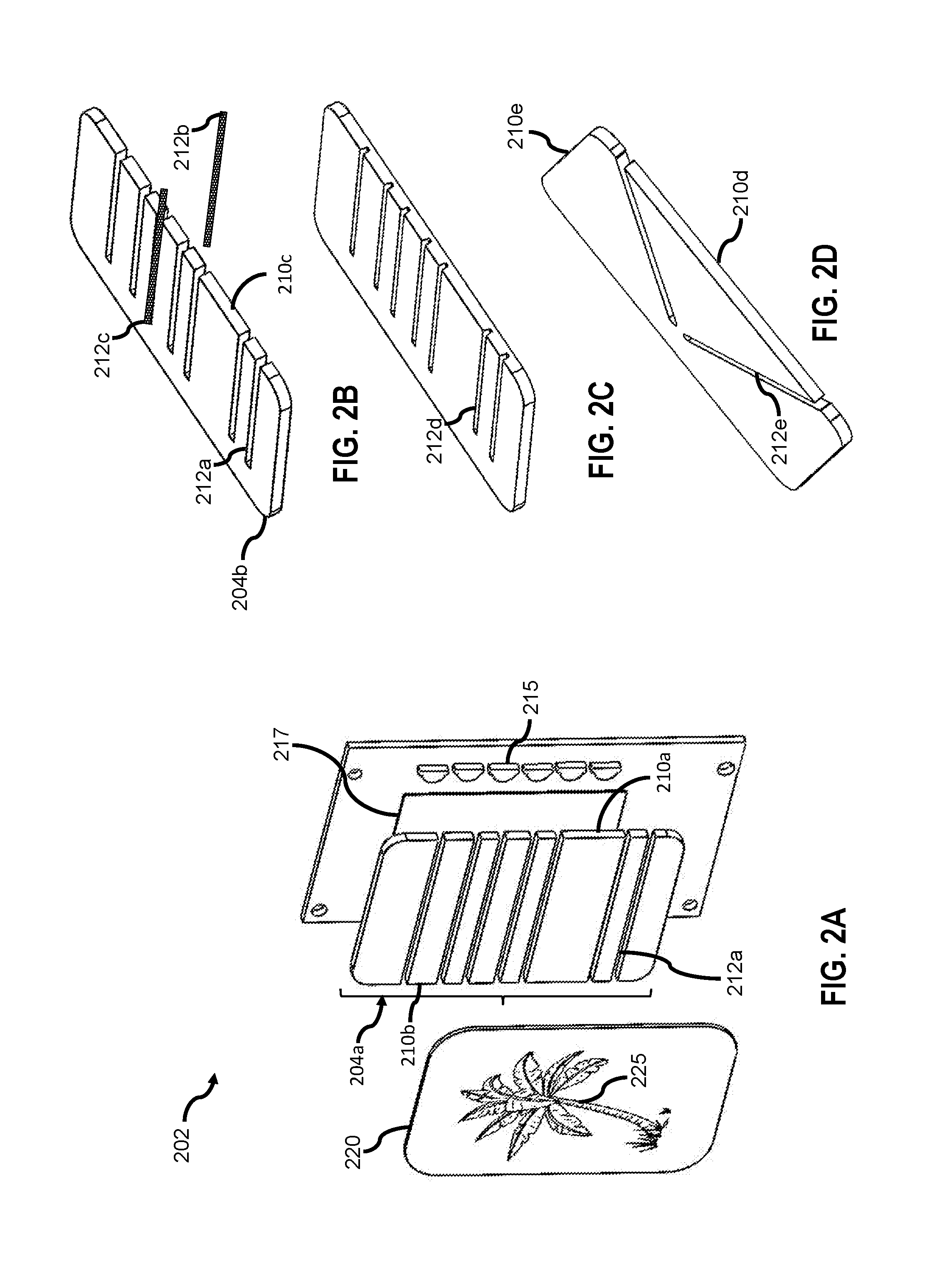
[0020]In another advantage, the translucent layer can enable users to express their aesthetic preferences with artwork. Aspects of this disclosure enable the translucent layer and artwork to be uniformly illuminated by segments. Artwork on a translucent layer enables aspects of the load controlled by the switch (e.g. location, purpose) to be announced or described to users. Several embodiment of this disclosure provide for light transmitted from a segmented backlight to generate di

Problems solved by technology

However, using light to effectively convey the operating point of a dimmer switch is challenging.
It is therefore difficult to make large uniformly illuminated features with an LED.
Materials in the dimmer switch (e.g. polymers) can also scatter light from LEDs, thereby causing indistinct indications.
Another challenge is to combine the illuminated indicators with the touch sensitive surface, thereby providing distinctly and uniformly illuminated regions of the touch sensitive surface.
U.S. Pat. No. 4,246,494 issued to Foreman and U.S. Pat. No. 4,246,494 issued to Grinsphoon discloses touch sensitive dimmer switches but do not address the challenge of illuminating one or more segments of the touch sensitive portion of the switch

Method used


Image

  • Smart illuminated electrical switch with touch control
  • Smart illuminated electrical switch with touch control
  • Smart illuminated electrical switch with touch control

Examples


Embodiment Construction

[0042]In the following detailed description, for purposes of explanation, numerous specific details are set forth to provide a thorough understanding of the various implementations of the present invention. Those of ordinary skill in the art will realize that these various implementations of the present invention are illustrative only and are not intended to be limiting in any way. Other implementations of the present invention will readily suggest themselves to such skilled persons having the benefit of this disclosure.

[0043]In addition, for clarity purposes, not all of the routine features of the implementations described herein are shown or described. One of ordinary skill in the art would readily appreciate that in the development of any such actual implementation, numerous implementation-specific decisions may be required to achieve specific design objectives. These design objectives will vary from one implementation to another and from one developer to another. Moreover, it wi...


PUM


Abstract

Internet connected electrical switches can benefit from an electronic rather than mechanical means to indicate their output power level. In one embodiment a touch-controlled dimmer switch is disclosed, including an interactive, uniformly illuminated bar of light, indicating the output power state of a dimmer switch. In response to a user moving their finger on a touch-sensitive front cover the dimmer switch illuminates corresponding regions with well-defined edges on a touch sensitive cover. The illuminated regions can be elongated, wider than a typical finger and encompass the most recently touched location, thereby providing improved feedback between the finger position on a touch sensitive surface and the operating point of an electrical switch. In several embodiments a segmented backlight is used to implement the interactive illuminated bar of light by uniformly illuminating the bounds of a touch region on the front surface of the switch corresponding to a particular output power state of the dimmer switch. Means are provided to produce closely spaced elongated illuminated regions with substantially uniform intensity and well-defined perimeters, well suited for internet connected smart light switches. In another aspect a translucent layer behind the touch sensitive surface can contain decorative and interchangeable artwork, illuminated by the segmented backlight.

Description

CROSS-REFERENCE TO RELATED APPLICATIONS[0001]None.FEDERALLY SPONSORED RESEARCH[0002]None.SEQUENCE LISTING[0003]None.FIELD OF THE INVENTION[0004]The present disclosure relates to touch displays and load control devices (e.g., wall mounted light switches) and more specifically to an electrical switch operable to uniformly illuminate a distinct bar of light behind a touch sensitive user input surface, indicative of the power output state of the switch).BACKGROUND OF THE INVENTION[0005]Several US states now require light switches to provide dimmer functionality to meet energy efficiency requirements. Modern light switches provide a variety of means to control the dimmer functionality (e.g. rotational knobs, mechanical sliders and buttons operable to increase and decrease the light intensity). More recently solid state touch-sensitive electrical switches (e.g. dimmer switches) have been developed. Touch-sensitive switches eliminate the need for moving parts and instead can use capacitive...

Claims


Application Information

Patent Timeline
IPC IPC(8): G06F3/0484G06F3/0488F21V8/00
CPCG06F3/04847G06F3/04886G02B6/0043G02B6/0068G02B6/0073G02B1/045G02B6/0021G02B6/0036G02B6/0038G02B6/0055G02B6/0078G06F1/3262G06F3/0416G06F3/0412
Inventor O'KEEFFE, JAMES THOMAS
Owner OKEEFFE JAMES THOMAS
Why Eureka
Try Eureka