
Periodic validation and health reports of disaster recovery plan

a disaster recovery and health report technology, applied in the field of disaster recovery systems, can solve the problems of limited recovery, uncertain components may become unavailable, and cannot be used in a multi-tier system full-scale recovery,

Active Publication Date: 2016-07-19
ORACLE INT CORP
View PDF19 Cites 6 Cited by
  • Summary
  • Abstract
  • Description
  • Claims
  • Application Information

AI Technical Summary

Benefits of technology

The patent describes a system for generating a disaster recovery plan for a multi-tier application that takes into account changes in the underlying components of the system. The system uses topology metadata to identify targets for relocation and generates an ordered set of instructions for relocating the application. This approach allows for a more comprehensive and automated recovery in the event of a disaster. The system also includes error management capabilities and can adapt to changes in the system components. Overall, the patent provides a solution for ensuring the resilience of large-scale systems in the event of unforeseen failures or natural disasters.

Problems solved by technology

Certain components may become unavailable due to scheduled maintenance, unforeseen device malfunctions, or some other source of failure.
However, recovery is limited to the storage tier, which may not allow for a full-scale recovery in multi-tier systems.
Restoring each layer of the stack after a disaster may be a tedious process involving complex execution and coordination between application, replication, and / or infrastructure experts.
However, in large-scale systems, it may become extremely difficult and error prone to maintain and update the custom scripts to accommodate frequent changes to the underlying system components.
Furthermore, homegrown scripts do not provide a standard, comprehensive set of error management capabilities in the event that a problem is encountered during disaster recovery.

Method used


Image

  • Periodic validation and health reports of disaster recovery plan
  • Periodic validation and health reports of disaster recovery plan
  • Periodic validation and health reports of disaster recovery plan

Examples


Embodiment Construction

[0015]In the following description, for the purposes of explanation, numerous specific details are set forth in order to provide a thorough understanding of the disclosure. It will be apparent, however, that the present invention may be practiced without these specific details. In other instances, structures and devices are shown in block diagram form in order to avoid unnecessarily obscuring the present invention.

General Overview

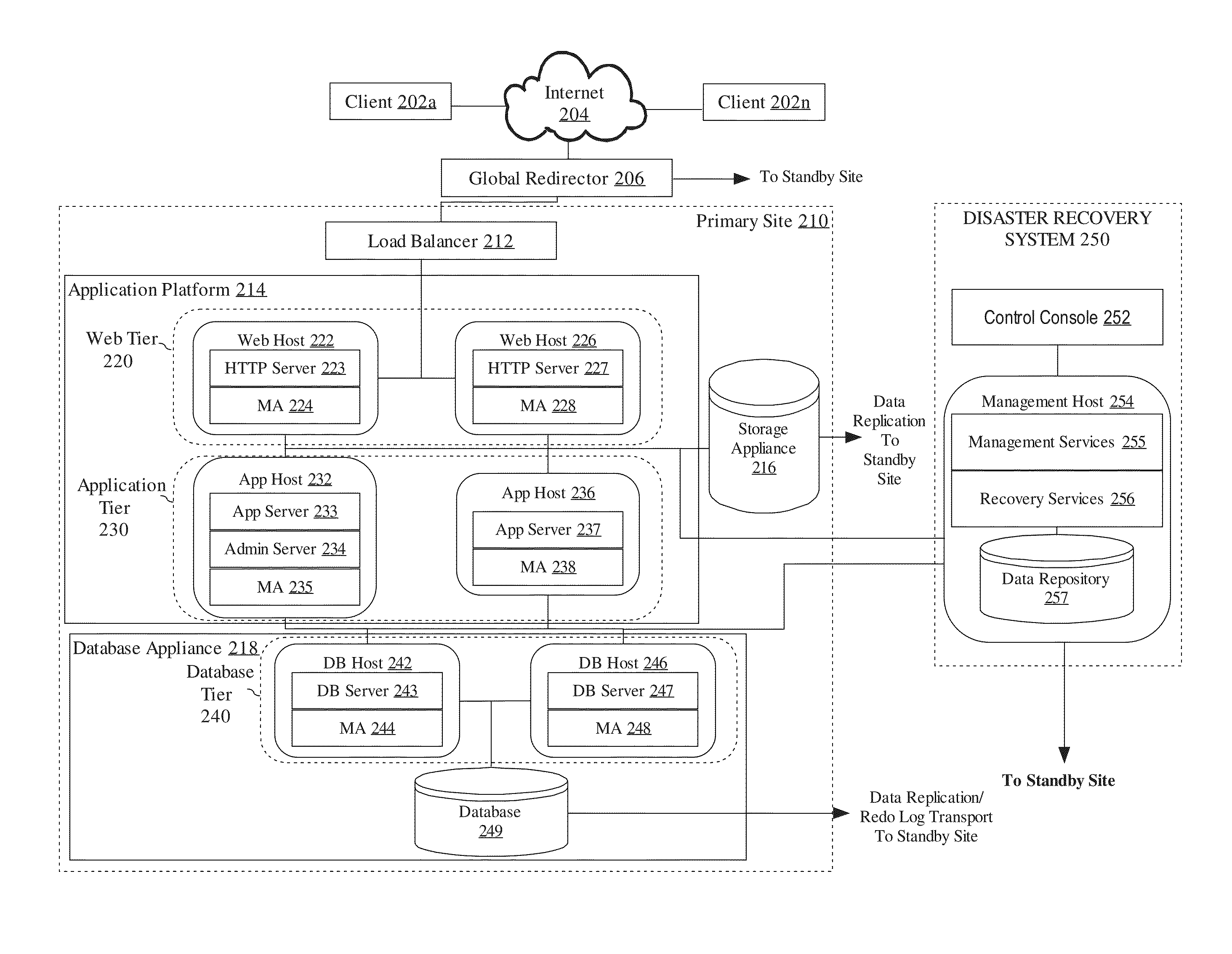
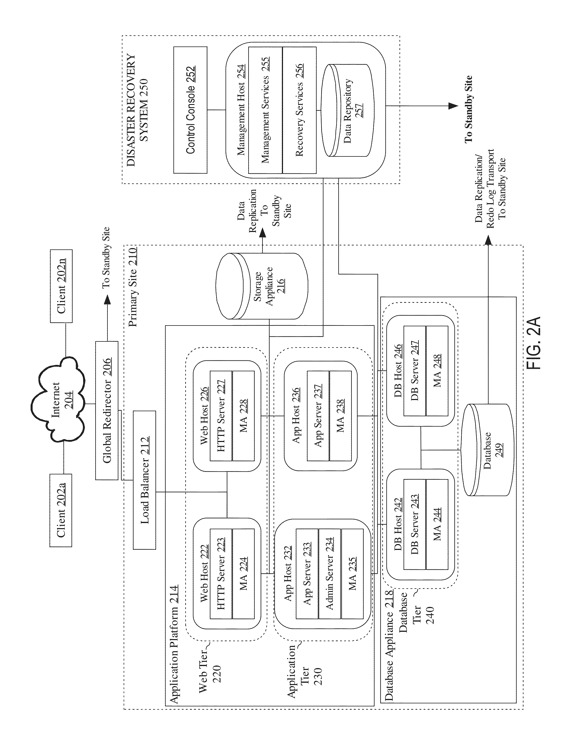
[0016]Techniques are described for dynamically generating a disaster recovery plan. The disaster recovery plan may be generated such that it takes into account the current state of deployment of a primary site, reacting to any changes that may have occurred. In an embodiment, a disaster recovery system maintains a set of topology metadata for a primary site and one or more standby sites. The topology metadata may be used to identify a set of targets from a plurality of tiers on the primary site and the one or more standby sites. Based, at least in part, on ...


PUM


Abstract

Techniques are described for validating a disaster recovery plan. In an embodiment, a request is received to perform a validation of a disaster recovery operation plan that includes a set of instructions for performing a disaster recovery operation with respect to a first site and a second site. In response to receiving the request to perform the validation of the disaster recovery operation plan, a set of one or more validation operations is performed with respect to the disaster recovery operation plan. Based on the set of one or more validation operations, a report is generated that identifies one or more issues that may prevent the disaster recovery operation plan from executing properly.

Description

CROSS-REFERENCE TO RELATED APPLICATIONS[0001]This application is related to application Ser. No. 14 / 265,572, filed Apr. 30, 2014, entitled “Dynamic Generation of Disaster Recovery Plan which React to Changes to an Underlying Topology”, and application Ser. No. 14 / 265,607 filed Apr. 30, 2014, entitled “Comprehensive Error Management for Disaster Recovery Operations”, the entire contents of which is hereby incorporated by reference as if fully set forth herein.FIELD OF THE DISCLOSURE[0002]The present disclosure relates, generally, to failover systems and, more specifically, to techniques for generating disaster recovery plans based on an underlying topology.BACKGROUND[0003]Enterprise deployments of large-scale systems may involve frequent changes to the underlying components within the system. For example, software and / or hardware components may be scaled up, scaled down, or scaled out. The state of the enterprise deployment may also change based on the availability of components or t...

Claims


Application Information

Patent Timeline
IPC IPC(8): G06F11/00G06F11/20H04L12/24
CPCG06F11/008G06F11/2023H04L41/0654H04L41/12H04L41/0873H04L41/145G06F11/1415G06F11/2025G06F11/2038G06F11/2094G06F11/3006G06F11/3051G06F11/0709G06F11/0793
Inventor SAMPATH, PRAVEENVIJJAPURAPU, RAMADESAI, MAHESHBORDE, SHEKHAR
Owner ORACLE INT CORP
Learn More