Dynamically adjustable airfoil system for road vehicles

a dynamic adjustable and airfoil technology, applied in vehicle body stabilisation, vehicle body streamlining, etc., can solve the problems of reducing the maneuverability, cornering speed and ride quality of vehicles, counterbalancing the tendencies of vehicles, and reducing the rear weight of vehicles, so as to facilitate dynamic adjustable positioning of airfoils, improve performance, and increase downforce

Active Publication Date: 2016-08-02
AL HUWAIDER MUSTAFA ALI HUSSAIN
View PDF14 Cites 39 Cited by
  • Summary
  • Abstract
  • Description
  • Claims
  • Application Information

AI Technical Summary

Benefits of technology

[0007]The dynamically adjustable airfoil system for road vehicles includes a pair of airfoils having their respective inner ends pivotally mounted to a central, vertical base on the rear of a road vehicle. An airfoil lift assembly is coupled to an outer end of each airfoil and to a rear wheel suspension system to facilitate dynamic adjustable positioning of the airfoils in response to movements of the suspension system. A split flap is piv...

Problems solved by technology

Such indirect transmission of downforce compromises the performance of the suspension system at high speeds, which reduces the vehicle maneuverability, cornering speed, and ride quality.
Such a system w...

Method used


Image

  • Dynamically adjustable airfoil system for road vehicles
  • Dynamically adjustable airfoil system for road vehicles
  • Dynamically adjustable airfoil system for road vehicles

Examples


Embodiment Construction

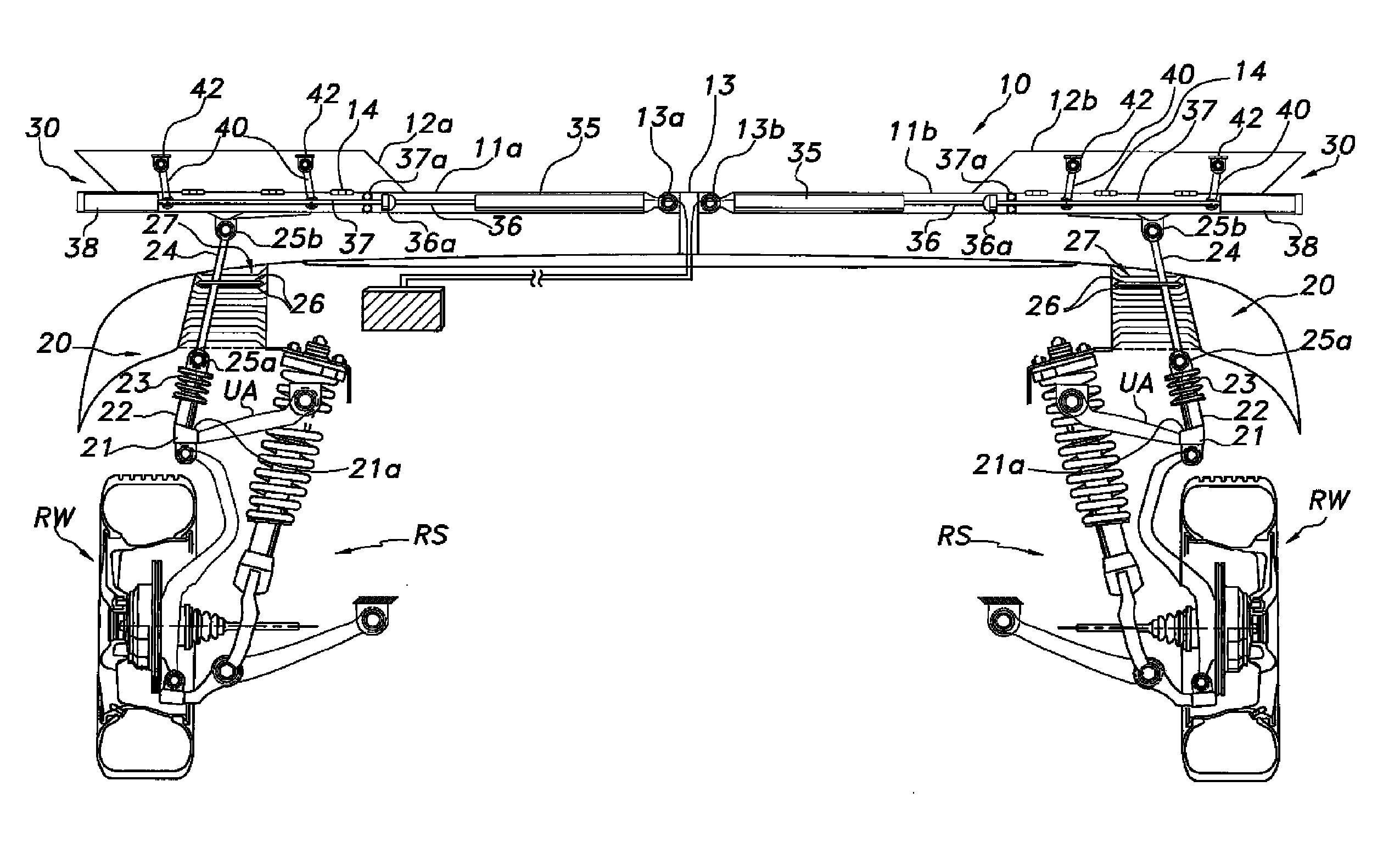
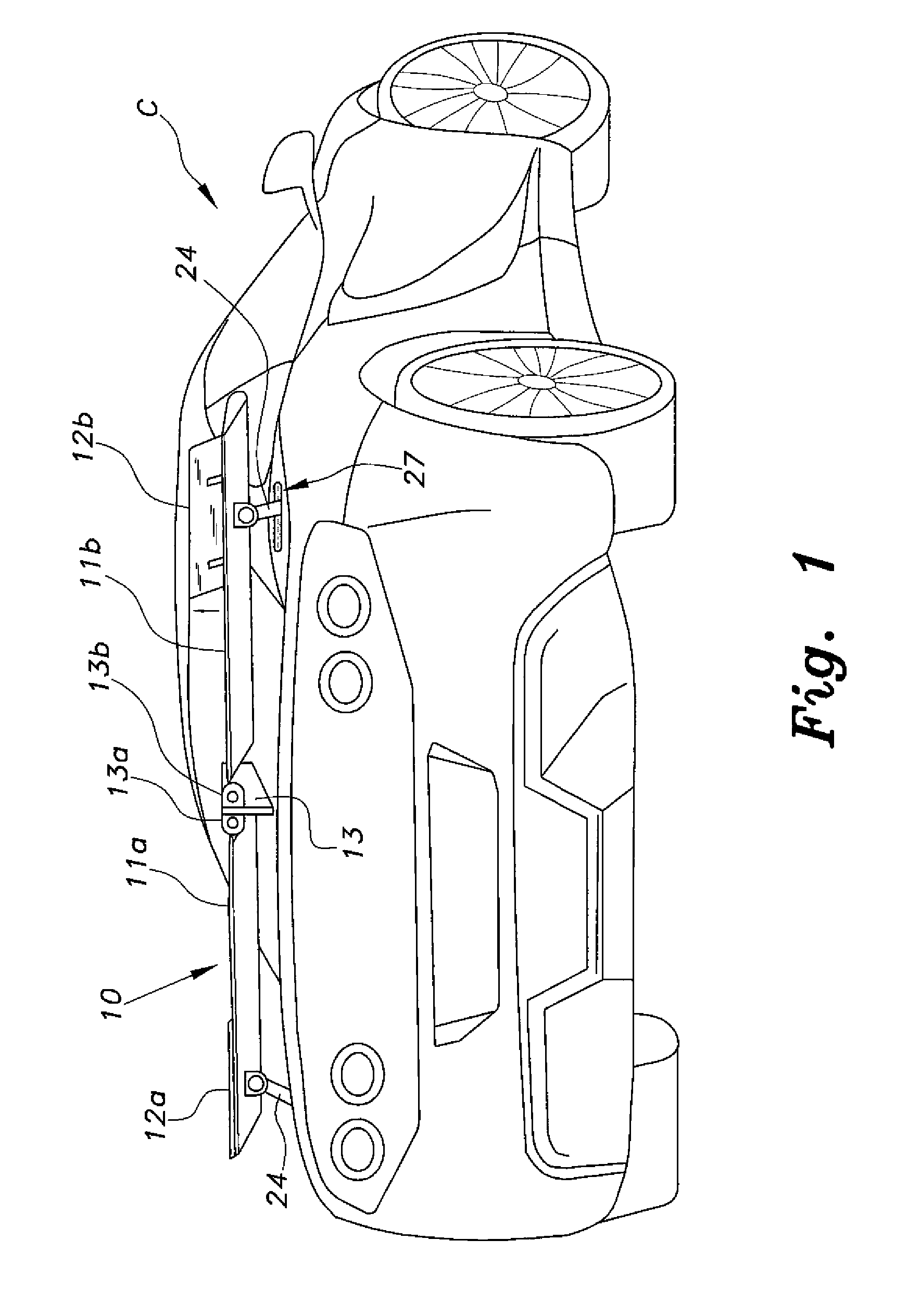
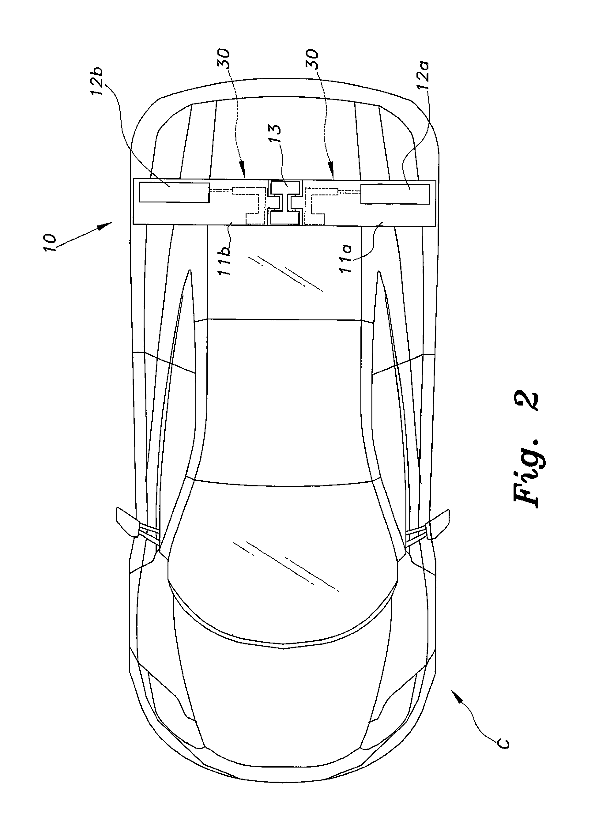
[0016]The dynamically adjustable airfoil system for road vehicles, generally referred to by the reference number 10 in the drawings, provides adjustable downforce to the rear suspension system RS of a road vehicle C to facilitate increased adherence to a road surface during movement and braking, and to improve overall performance and handling. The dynamically adjustable airfoil system 10 includes a pair of left and right airfoils or spoilers 11a, 11b pivotally mounted with respect to each other, and an airfoil lift assembly 20 coupled at one end to a conventional high-mounted, double wishbone suspension system RS mounted to the rear wheels RW of a road vehicle at one end and to the respective airfoil 11a, 11b at the opposite end. An example of the double wishbone suspension system RS can be found in U.S. Pat. No. 7,234,712, issued Jun. 26, 2007 to Yamazaki et al., which is hereby incorporated by reference in its entirety. The coupling of the airfoil lift assembly 20 permits the resp...


PUM


Abstract

The dynamically adjustable airfoil system for road vehicles includes a pair of airfoils having their respective inner ends pivotally mounted to a central, vertical base on the rear of a road vehicle. An airfoil lift assembly is coupled to an outer end of each airfoil and to a rear wheel suspension system to facilitate dynamic adjustable positioning of the airfoils in response to movements of the suspension system. A split flap is pivotally mounted to each airfoil. A split flap actuator assembly is mounted inside each airfoil and coupled to a corresponding split flap to selectively and independently open or close the respective split flap. Opening of the split flap to various angles increases downforce exerted on the rear suspension system for improved performance. A controller controls deployment and angular disposition of the split flaps, depending on driving conditions.

Description

CROSS-REFERENCE TO RELATED APPLICATION[0001]This application claims the benefit of U.S. Provisional Patent Application Ser. No. 62 / 116,292, filed Feb. 13, 2015.1. FIELD OF THE INVENTION[0002]The present invention relates to motor vehicle performance enhancement systems, and particularly to a dynamically adjustable airfoil system for road vehicles that adjusts the aerodynamic profile of the road vehicle to selectively increase downforce on the vehicle in response to maneuvering conditions.2. DESCRIPTION OF THE RELATED ART[0003]High performance road vehicles have external body shapes that serve two general objectives. The first objective is to minimize running resistance by minimizing aerodynamic drag. The second objective is to maximize downforce by maximizing the downward vertical aerodynamic load component, especially at the wheels to insure that they remain on the surface as much as possible.[0004]In order to increase the downforce, aerodynamic projecting elements are typically mo...

Claims


Application Information

Patent Timeline
IPC IPC(8): B62D35/00B62D37/02
CPCB62D35/007B62D37/02B60G2800/01B60G2800/16B60G17/00B60G99/00B60G2204/4308B60G2300/27
Inventor AL-HUWAIDER, MUSTAFA ALI HUSSAIN
Owner AL HUWAIDER MUSTAFA ALI HUSSAIN
Why Eureka
Try Eureka