
Truss and wall stabilizer

a technology for stabilizing walls and trusses, applied in the direction of girders, joists, trusses, etc., can solve the problems of preventing the lateral braces from being removed, unable to provide support after the removal of braces, and wasting time and money

Active Publication Date: 2016-08-02
RENO HOWARD
View PDF13 Cites 9 Cited by
  • Summary
  • Abstract
  • Description
  • Claims
  • Application Information

AI Technical Summary

Benefits of technology

The apparatus simplifies truss installation, reduces labor costs, ensures accurate spacing, and provides additional support against buckling forces, enhancing worker safety and efficiency by eliminating the need for temporary blocks and reducing material waste.

Problems solved by technology

While these pre-manufactured trusses are strong and reliable in service, during construction they can topple if they are not properly supported.
This temporary attachment and subsequent removal of lateral braces is time consuming and thus expensive.
Moreover, while this method of lateral bracing supports the trusses during construction, it provides no support after the braces are removed.
However, these have generally been elaborate devices that were too expensive and cumbersome to find practical application in the field.
Moreover, these were typically temporary devices that had to be removed before construction was completed, with attendant labor costs, and thus they did not provide any post-construction support of the truss.

Method used


Image

  • Truss and wall stabilizer
  • Truss and wall stabilizer
  • Truss and wall stabilizer

Examples


Embodiment Construction

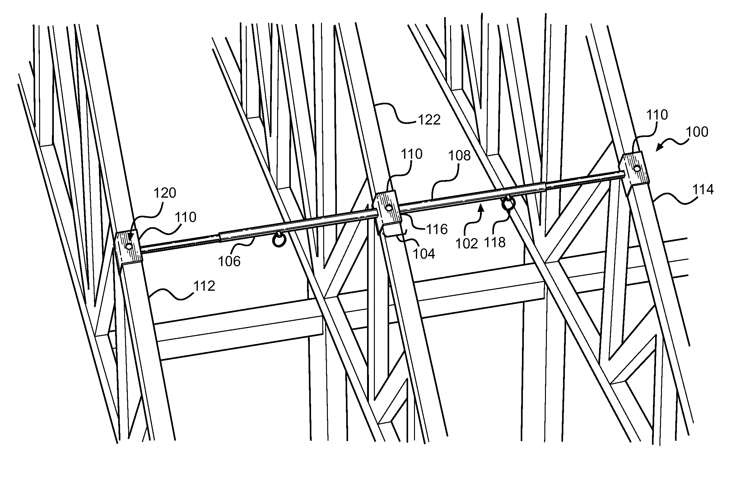
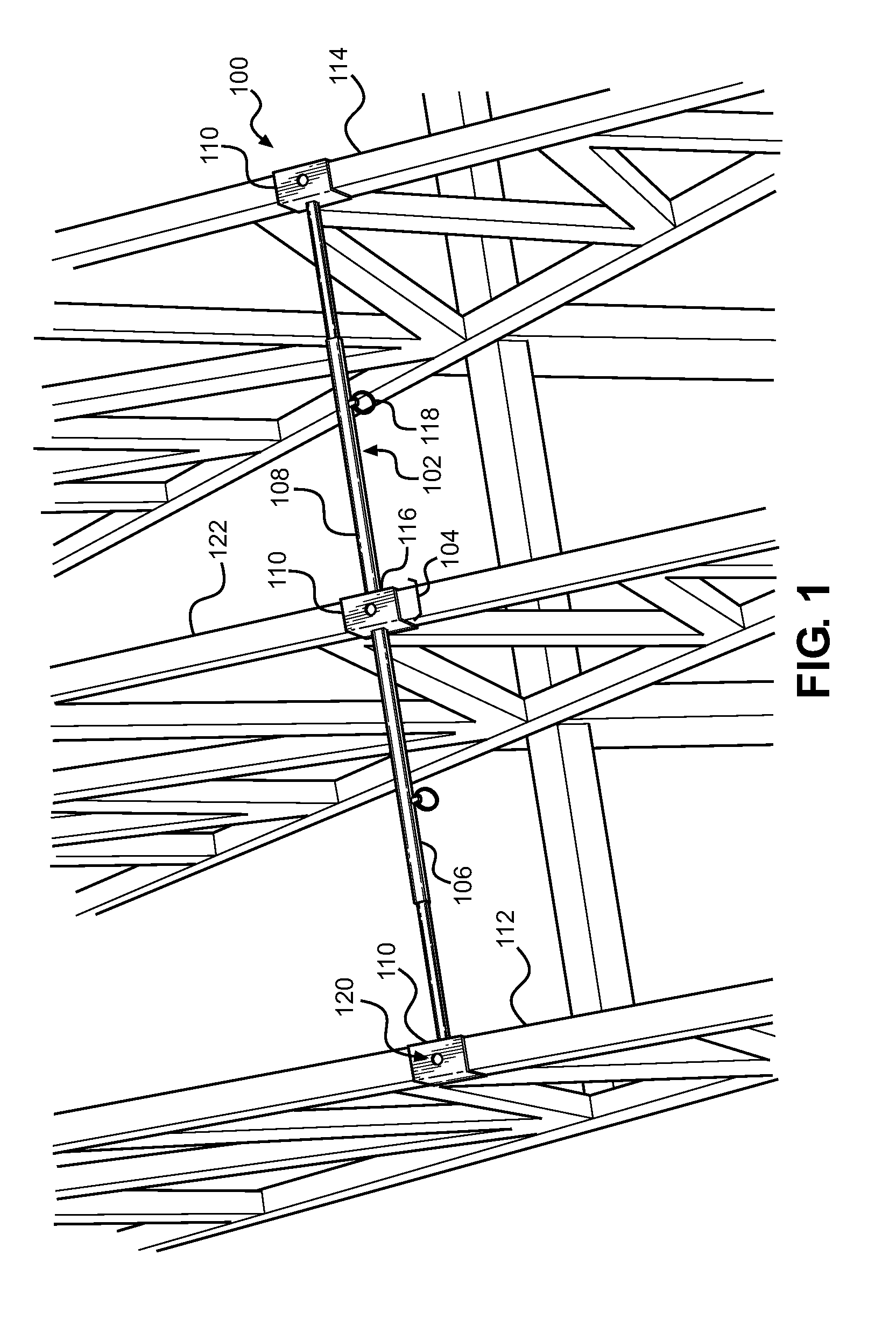
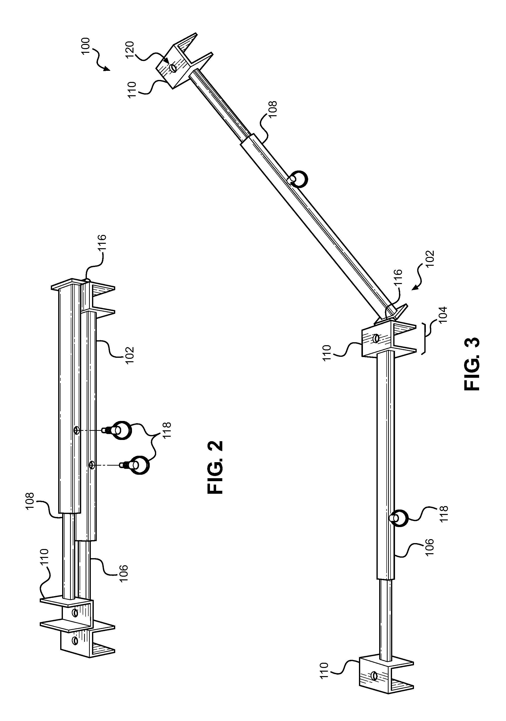
[0022]Reference is made herein to the attached drawings. Like reference numerals are used throughout the drawings to depict like or similar elements of the apparatus for stabilizing and spacing truss members. For the purposes of presenting a brief and clear description of the present invention, the preferred embodiment will be discussed as used for installing a roofing structure. The figures are intended for representative purposes only and should not be considered to be limiting in any respect.

[0023]The present invention aids in both the installation and stabilization of roof trusses. The invention enables users to hold trusses in place in an accurate and central position until secured to a roof. The invention eliminates the need to cut temporary blocks or boards for spacing and saves time for users by not having to lay out lineal boards for spacing. The invention can save the user a significant amount of time and prevents wasted material.

[0024]Referring now to FIGS. 1 and 3, there...


PUM


Abstract

An apparatus for spacing and stabilizing truss members is provided. The apparatus includes an elongated channel member having a middle portion, a first arm portion, and a second arm portion. The first arm portion and second arm portion extend outwardly from the middle portion. A plurality of U-shaped clamp members may be disposed along the length of the elongated channel member. At least one U-shaped clamp member can be attached to a central truss member providing a centered layout for spacing a first truss member in relation to a second truss member. A hinge member may pivotally attach the middle portion of the elongated channel member to the second arm portion, allowing the second arm portion to swing onto an additional third truss member.

Description

CROSS REFERENCE TO RELATED APPLICATION[0001]This application claims the benefit of U.S. Provisional Application No. 62 / 025,808 filed on Jul. 14, 2014. The above identified patent application is herein incorporated by reference in its entirety to provide continuity of disclosure.FIELD OF THE INVENTION[0002]The invention generally relates to an apparatus for stabilizing roof trusses. More particularly, the present invention relates to an apparatus for stabilizing and spacing roof trusses during construction and thereafter.BACKGROUND OF THE INVENTION[0003]Pre-manufactured wooden trusses greatly facilitate the construction of buildings and other structures. While these pre-manufactured trusses are strong and reliable in service, during construction they can topple if they are not properly supported. Moreover, to ensure that the trusses perform properly in service, it is important to make sure that they are properly spaced.[0004]Presently, when trusses are used in construction they are p...

Claims


Application Information

Patent Timeline
Patent Type & Authority Patents(United States)
IPC IPC(8): E04C3/11E04G21/18E04C3/02
CPCE04C3/02E04G21/1891E04C2003/026
Inventor RENO, HOWARD
Owner RENO HOWARD
Learn More