Hinge structure

a technology of hinges and hinges, applied in the direction of hinges, door/window fittings, instruments, etc., can solve the problems of easy damage of conventional stands, limited rotational angle, and large space occupation of open structures, and achieve the effect of simplifying the structure and the manufacturing process

Active Publication Date: 2016-08-02
LIANHONG TECH
View PDF24 Cites 45 Cited by
  • Summary
  • Abstract
  • Description
  • Claims
  • Application Information

AI Technical Summary

Benefits of technology

[0007]An object of the invention is to provide a hinge structure including a sandwiched torque member which simplifies the structure and the manufacturing process.

Problems solved by technology

Since the tablets are often used by both hands, users feel tired quickly.
However, such a conventional stand has an opened structure which often occupies a considerable space and a limited rotational angle.
The conventional stand is also easily damaged due to impact.
However, the hinge structure still uses a torque positioning device composed of too many elements to position the stand.

Method used


Image

  • Hinge structure
  • Hinge structure
  • Hinge structure

Examples


Embodiment Construction

[0019]The following description is of the best-contemplated mode of carrying out the invention. This description is made for the purpose of illustrating the general principles of the invention and should not be taken in a limiting sense. The scope of the invention is best determined by reference to the appended claims.

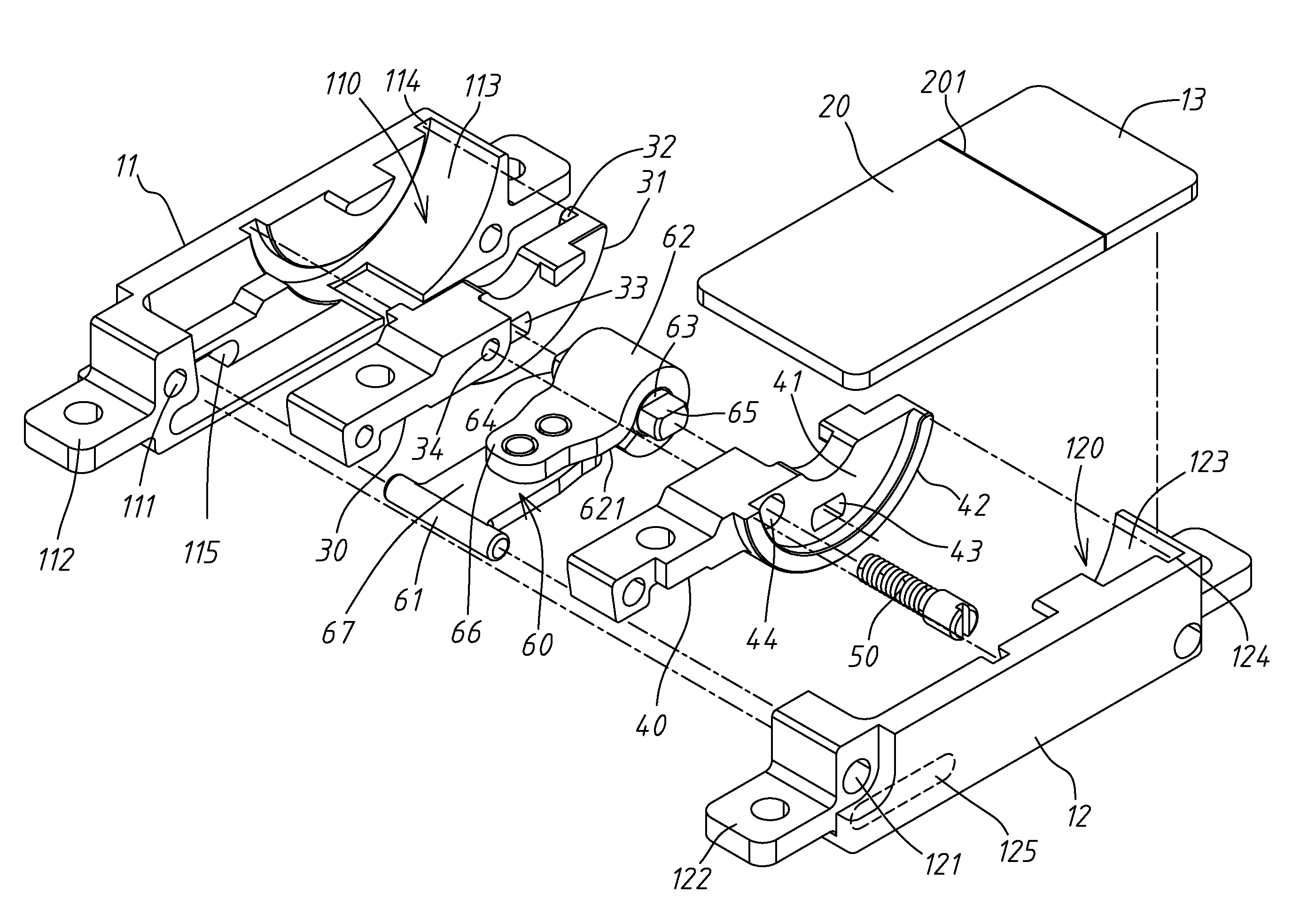
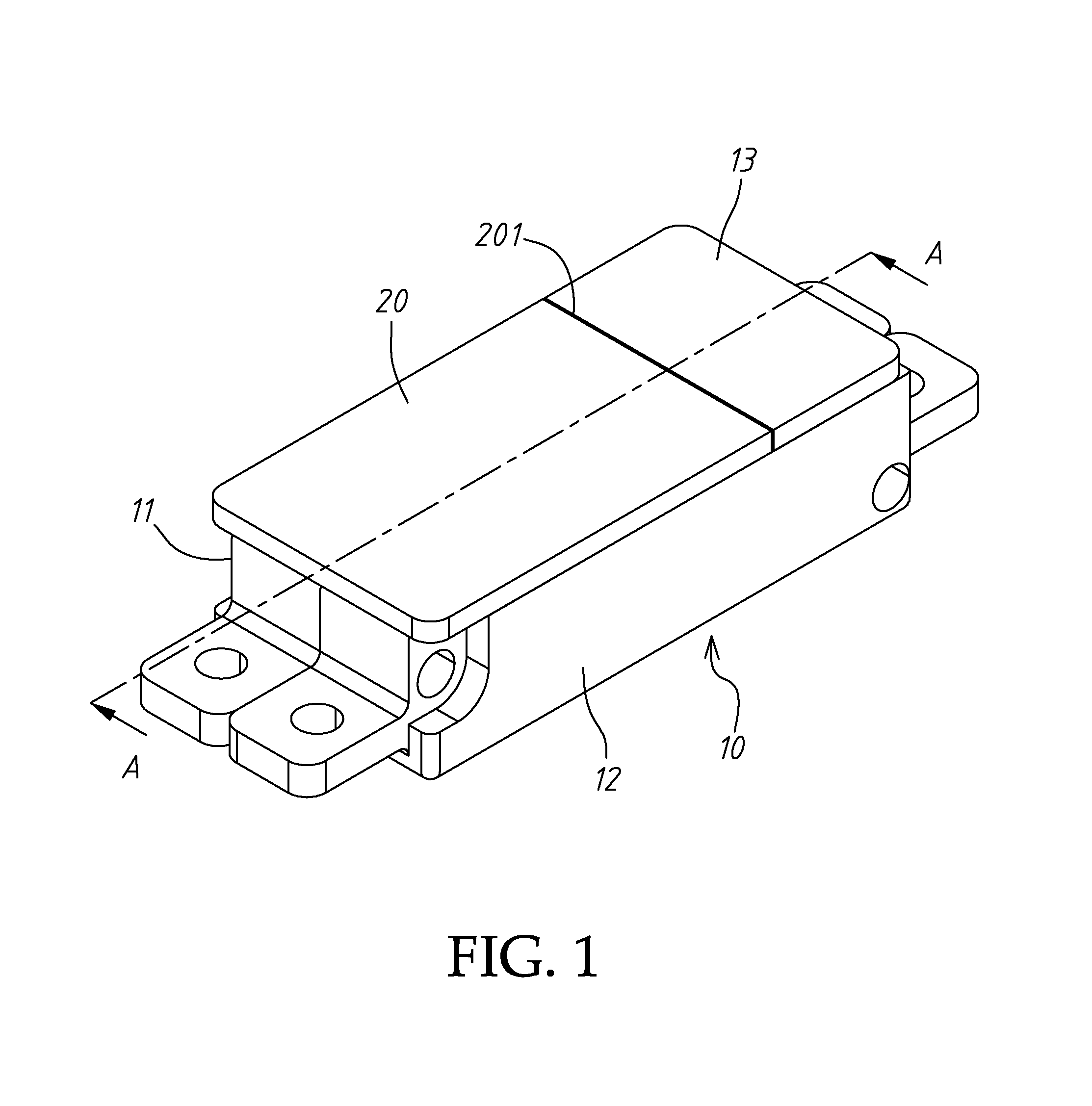
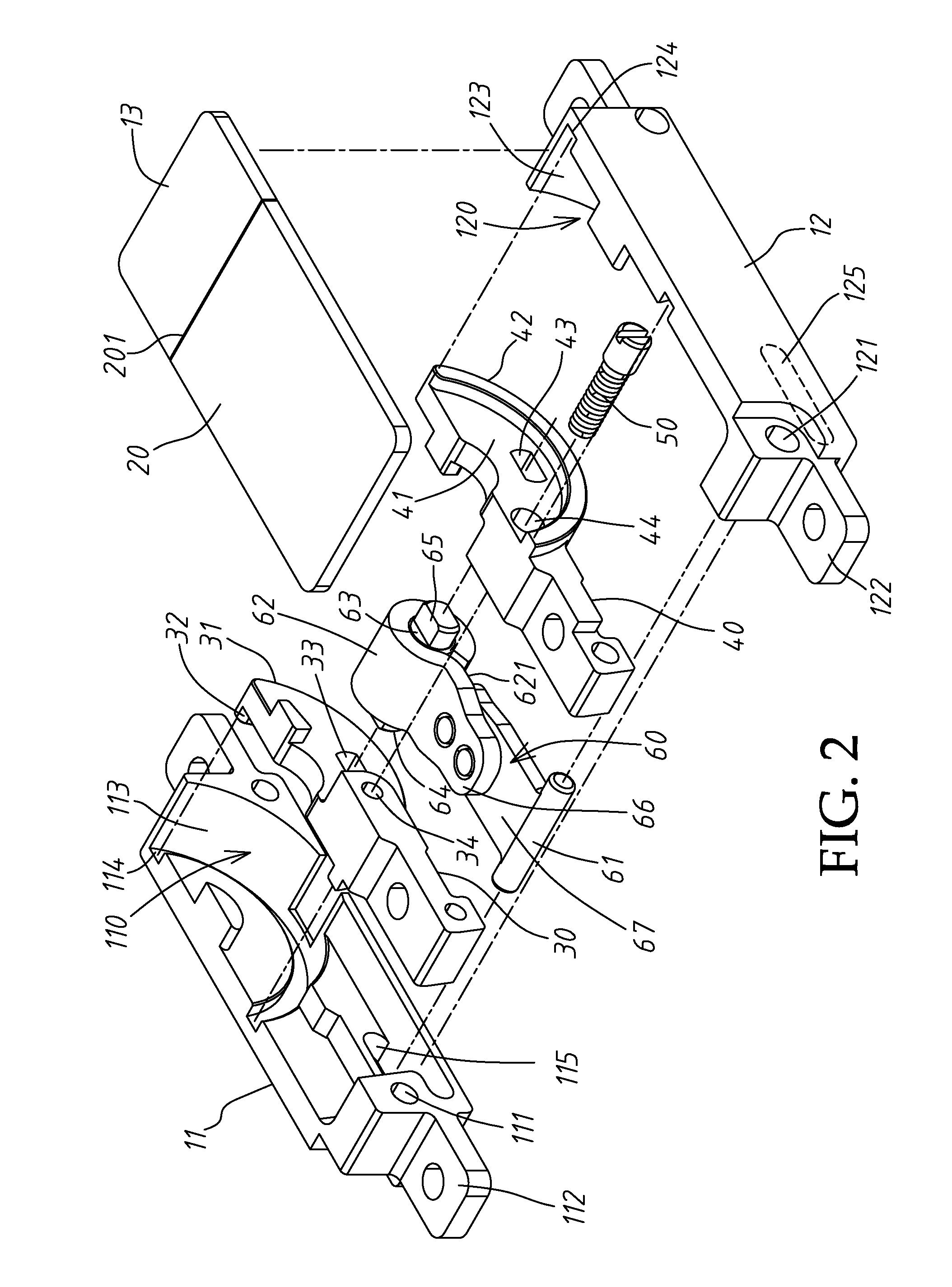
[0020]Referring to FIGS. 1 to 3, a hinge structure of the invention includes a housing 10. The housing 10 includes an opening formed on a top thereof and an inner space. The housing 10 further includes two half-housings 11 and 12 forming the inner space. The two half-housings 11 and 12 are assembled together through bolts screwed into holes 111 and 121. The half-housing 11 has an extending positioning plate 112, and the half-housing 12 has an extending positioning plate 122. The housing 10 further includes a cover 13 configured to cover a portion of the opening and a lifting member 20 disposed in an electronic device and configured to cover the other portion of the ope...


PUM


Abstract

A hinge structure includes a housing comprising two half-housings disposed opposite, an opening formed on a top thereof, an inner space formed by the half-housings, a cover plate configured to cover a portion of the top and a lifting member disposed in an electronic device to cover the other portion of the top, wherein a gap is formed between the cover plate and the lifting member, each of the half housing comprises a depression and a guiding groove formed in front of the depression, and the two depressions form the inner space; two half-driving members opposite disposed, mounted in the inner space and connected to the lifting member so that the half-driving members are assembled to each other and actuate in the inner space; and a sandwiched torque member disposed between the half-driving members and comprising a guiding rod having two ends movably inserted into the half-driving members and an axial torque tube having a preset notch, wherein the axial torque tube is tightly fitted to a shaft connected to the half-driving members.

Description

BACKGROUND OF THE INVENTION[0001]1. Field of the Invention[0002]The invention relates to a hinge structure, and more particularly to a hinge structure used in an electronic devices and positioning a lifting member in any angular position through a simple sandwiched member.[0003]2. Description of the Related Art[0004]Electronic devices such as tablets which are portable devices and used to transmit or control data by touching their screens. Since the tablets are often used by both hands, users feel tired quickly. When the tablets are put on knee, it is easy to slide or shake. To solve such a problem, a stand is used to support the tablets in a predetermined angle for operation.[0005]Conventional stands for supporting electronic devices are usually pivoted to the electronic devices at one end, and the other end becomes free end. The stand can be folded and received in the electronic device. The free end is rotated to a desired angle with respect to the pivoted end when the electronic ...

Claims


Application Information

Patent Timeline
Patent Type & Authority Patents(United States)
IPC IPC(8): E05D1/04E05D3/18E05D11/00G06F1/16E05D11/08
CPCE05D3/183E05D11/0054E05D11/082G06F1/1681
Inventor CHEN, CHIA-HUICHEN, YEN-TINGLIN, TZU-YU
Owner LIANHONG TECH
Why Eureka
Try Eureka