Radio reception device and radio reception method in radio communication system

a radio communication system and radio reception technology, applied in the field of radio communication system, can solve problems such as exhaustion of frequency resources, and achieve the effect of effectively suppressing the influence of interference waves and enhancing interference suppression performan

Active Publication Date: 2016-08-02
NEC CORP
View PDF9 Cites 2 Cited by
  • Summary
  • Abstract
  • Description
  • Claims
  • Application Information

AI Technical Summary

Benefits of technology

[0017]According to the present invention, it is possible to effectively suppress the influence of interfering waves from a different radio system and to enhance interference suppression performance.

Problems solved by technology

In next-generation radio communication systems, there are concerns over exhaustion of frequency resources as the transmission rates increase with wider bandwidths and systems are increasingly diversified.

Method used


Image

  • Radio reception device and radio reception method in radio communication system
  • Radio reception device and radio reception method in radio communication system
  • Radio reception device and radio reception method in radio communication system

Examples


first exemplary embodiment

1. First Exemplary Embodiment

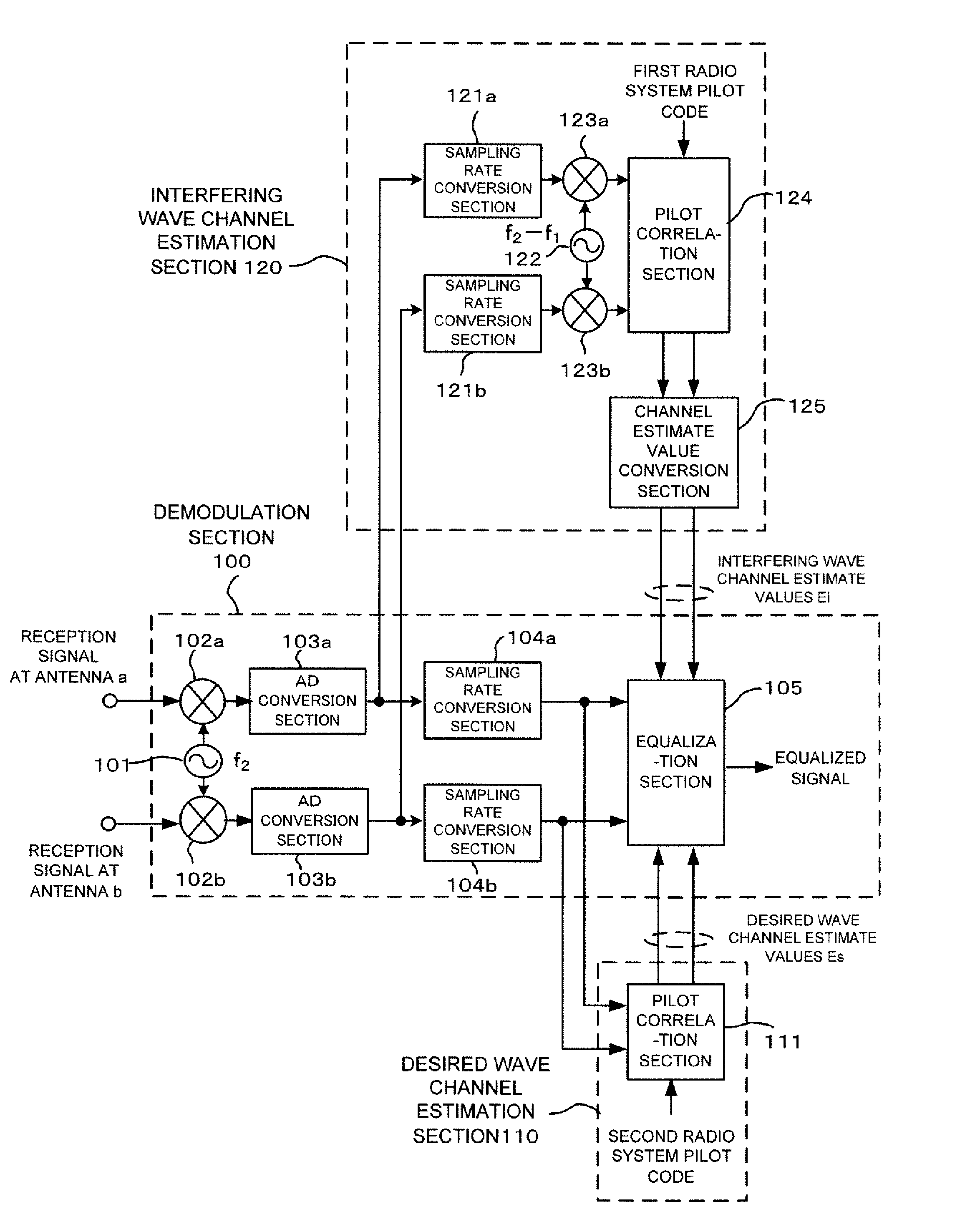
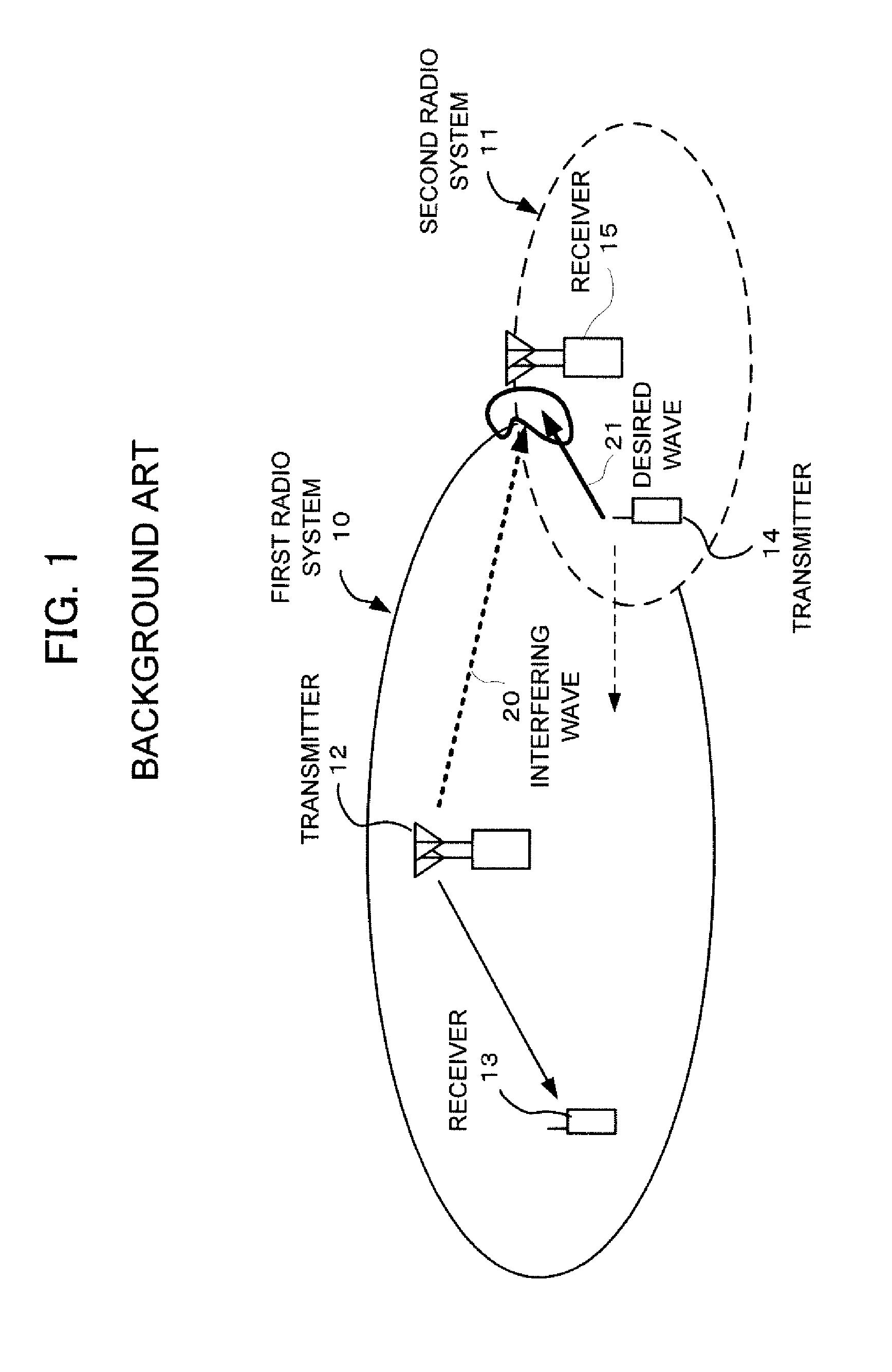
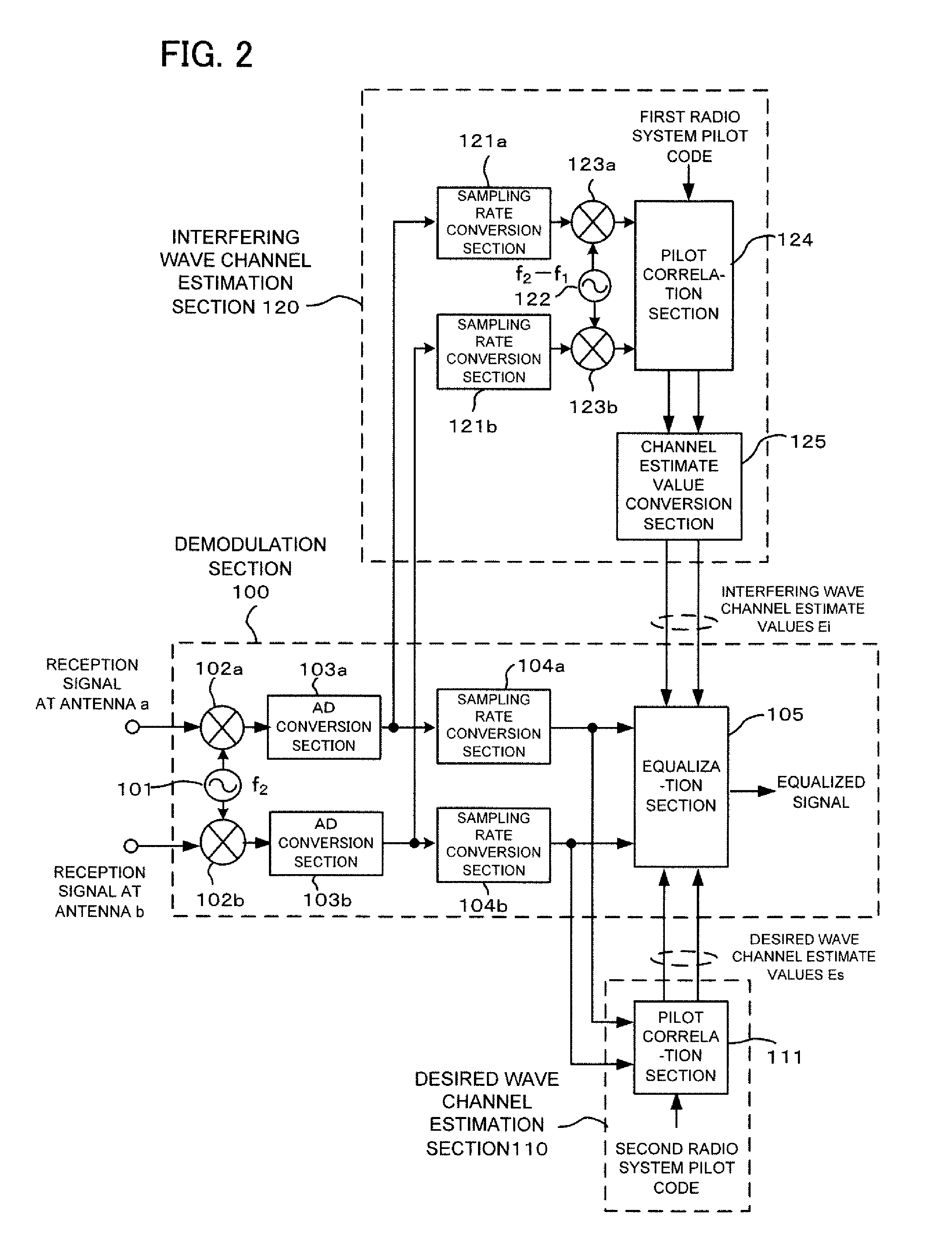
[0030]Hereinafter, a first exemplary embodiment of the present invention will be described in detail with reference to drawings. Single-carrier and multi-carrier transmission systems will be illustrated as an example of radio access schemes, and it will be assumed that the radio reception device of the second radio system 11 in FIG. 1 shares a frequency band assigned to the first radio system 10. The first radio system 10 and the second radio system 11 in FIG. 1 have different communication parameters, and here demodulation parameters (center frequency, sampling rate, and system bandwidth) are assumed to be different. Note that the radio reception device of the second radio system 11 is also applicable to a reception section of any of a mobile station and a base station in the second radio system 11 in FIG. 1.

1.1) Configuration

[0031]Referring to FIG. 2, the radio reception device according to the first exemplary embodiment of the present invention includ...

second exemplary embodiment

2. Second Exemplary Embodiment

[0063]Hereinafter, a second exemplary embodiment of the present invention will be described in detail with reference to drawings. However, it is assumed that the radio reception device of the second radio system in FIG. 1 shares a frequency band assigned to the first radio system 10. The radio reception device according to the second exemplary embodiment of the present invention obtains channel estimates and performs equalization processing through processing in frequency domain, assuming an OFDM (Orthogonal Frequency Division Multiplexing) based transmission scheme. The first radio system 10 and the second radio system 11 in FIG. 1 have different communication parameters, and here demodulation parameters (center frequency, subcarrier intervals, and system bandwidth) are assumed to be different. Note that the radio reception device of the second radio system 11 is also applicable to a reception section of any of a mobile station and a base station in th...

third exemplary embodiment

3. Third Exemplary Embodiment

[0087]The above-described exemplary embodiments illustrate radio reception devices in the first radio system 10 and the second radio system 11 shown in FIG. 1 as examples. However, the present invention is also applicable even if a plurality of radio systems of different types exist and a plurality of radio systems of the same type also exist. Hereinafter, a description will be given of a case, as a third exemplary embodiment of the present invention, where two radio systems of the same type (first and second radio systems) and two radio systems of different types (third and fourth radio systems) exist, and where a radio reception device according to the present exemplary embodiment belongs to the second radio system.

[0088]Referring to FIG. 11, the radio reception device according to the present exemplary embodiment includes a frequency oscillator 1001, frequency conversion sections 1002a and 1002b, AD conversion sections 1003a and 1003b, sampling rate c...


PUM


Abstract

A radio reception device and a radio receiving method are provided that, when a frequency band assigned to a different radio system is shared, can effectively suppress the influence of interfering waves from this different radio system. A radio reception device is one in a second radio system (11) that can use a frequency band assigned to a first radio system (10), and includes: a desired wave channel estimation section (110) that generates, based on reception signals, first channel estimate values (Es) of interfering wave components arriving from the first radio system, which uses a different communication scheme from that of the second radio system; an interfering wave channel estimation section (120) that generates, based on the reception signals, second channel estimate values (Ei) of desired wave components received through the communication scheme of the second radio system; and an equalization section (105) that suppresses the interfering wave components by using the first and second channel estimate values.

Description

CROSS-REFERENCE TO RELATED PATENT APPLICATIONS[0001]This application is a National Stage Entry of International Application No. PCT / JP2012 / 007161, filed Nov. 8, 2012, which claims priority from Japanese Patent Application No. 2011-261308, filed Nov. 30, 2011. The entire contents of the above-referenced applications are expressly incorporated herein by reference.TECHNICAL FIELD[0002]The present invention relates to a radio communication system and, more particularly, to a radio reception device and a radio receiving method utilizing a frequency band assigned to radio communication systems of different radio schemes.BACKGROUND ART[0003]In next-generation radio communication systems, there are concerns over exhaustion of frequency resources as the transmission rates increase with wider bandwidths and systems are increasingly diversified. In such circumstances, cognitive radios have been studied that identify surrounding radio wave environments and users' needs to autonomously optimize ...

Claims


Application Information

Patent Timeline
Patent Type & Authority Patents(United States)
IPC IPC(8): H04B1/10H04L25/02H04J11/00H04W16/14
CPCH04J11/0023H04B1/1027H04L25/0202H04W16/14
Inventor FUTATSUGI, YASUNORI
Owner NEC CORP
Why Eureka
Try Eureka