Systems and methods for recording simultaneously visible light image and infrared light image from fluorophores

a technology of visible light and infrared light, which is applied in the field of systems and methods for recording simultaneously visible light image and infrared light image from fluorophores, can solve the problems of inability to use, inadequate intravascular imaging sensitivity, and no imaging system available commercially that is optimized for near infrared fluorescence based resection of tumors

Active Publication Date: 2016-08-02
CEDARS SINAI MEDICAL CENT
View PDF23 Cites 24 Cited by
  • Summary
  • Abstract
  • Description
  • Claims
  • Application Information

AI Technical Summary

Problems solved by technology

However, due to the general absence of applications of fluorescent tumor ligands in surgical oncology, currently there are no imaging systems available commercially that are optimized for near infrared (NIR) fluorescence based resection of tumors.
These systems have adequate sensitivity for intravascular imaging, but are not practical for use in, for example, targeted tumor-specific NIR fluorescence.
For example, Fluobeam is hand held device with no overlay of white light images but is not designed for practical use as a surgical tool that requires HD quality images in white light, maneuverability, magnification, illumination, and automated co-registration of NIR images.
As the fluorescent excitation and emission of NIR dyes such as ICG have a very narrow stokes shift, the long pass filter causes a significant loss of fluorescent light (FIG. 1), and subsequent detection sensitivity.
This results in markedly less fluorescent signal, making currently marketed systems inadequate for detection.
Additionally, these systems can be cumbersome to use in the clinical setting, due to the fact that there are two camera attachments, and require a complete change in the existing setup.

Method used


Image

  • Systems and methods for recording simultaneously visible light image and infrared light image from fluorophores
  • Systems and methods for recording simultaneously visible light image and infrared light image from fluorophores
  • Systems and methods for recording simultaneously visible light image and infrared light image from fluorophores

Examples


example 1

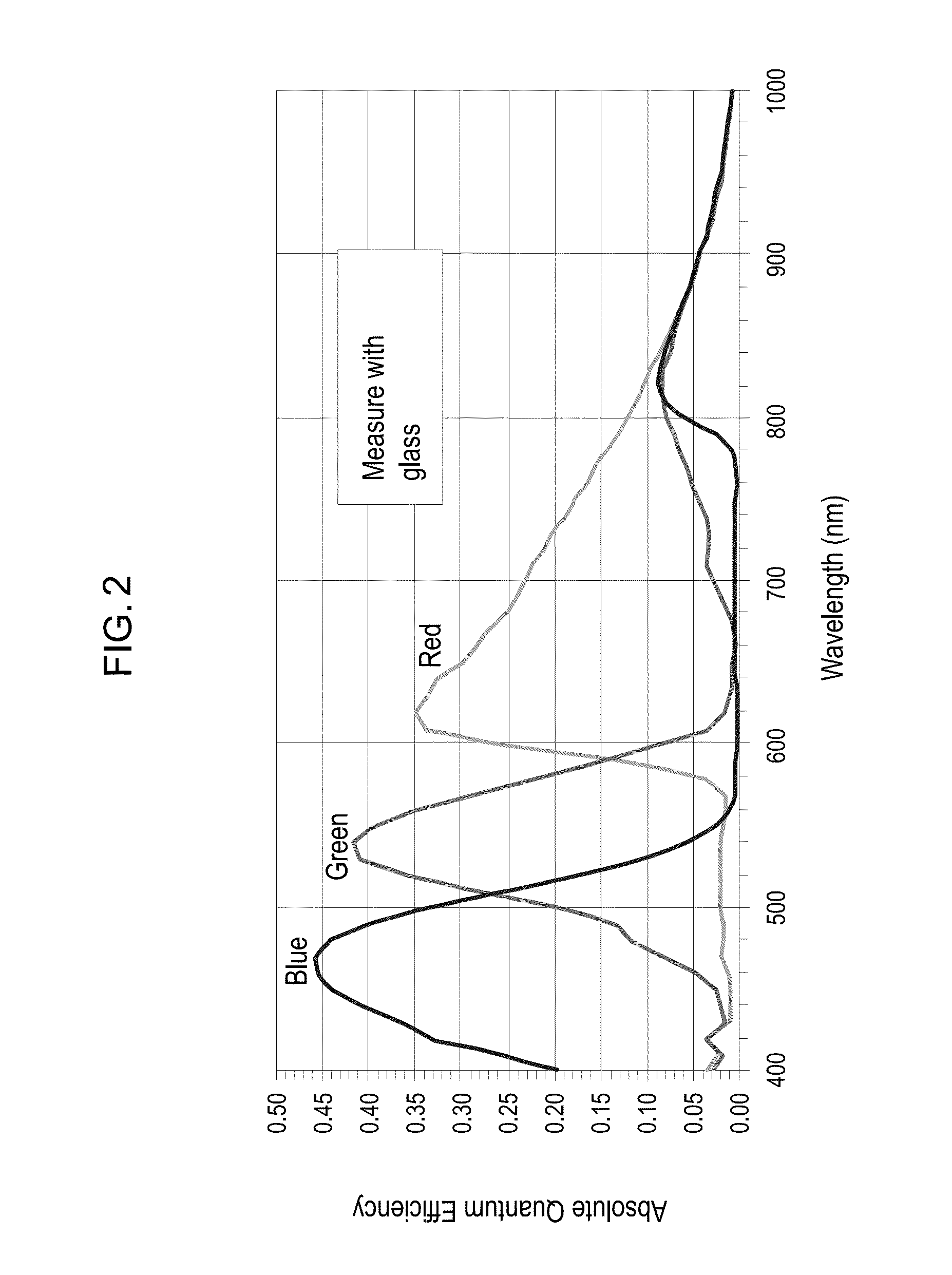
[0163]Charged Coupled Devices (CCDs) or Complementary metal-oxide-semiconductor (CMOS) sensors used in the cameras have a broad spectrum of sensitivity ranging from 400 nm to 1000 nm (FIG. 2). All the Red, Green and Blue sensors show sensitivity in the 800-1000 nm of wavelength. The commercially available cameras have a color filter array (CFA) or color filter mosaic (CFM) as shown in FIG. 3 on top of a sensor to collect color information from the image. In addition to this filter array there is an additional NIR short pass filter to cutoff light from 700-1000 nm of wavelength.

example 2

[0164]We use the sensitivity of Red, Green and Blue pixels in near infrared region (NIR) to detect infrared fluorescence. A visible light source illuminates the sample of interest. Also, a laser is used as the excitation light for the infrared fluorophore in tissue, and the emission light from the infrared fluorophore is detected by a CCD camera. Meanwhile, the excitation light is filtered before reaching the CCD camera to avoid interfering detection of the emission light. An image frame is captured when the laser is on (on-frame). Another image frame is captured when the laser is off (off-frame). The on-frame detects both visible light and infrared fluorescence, while the off-frame detects only visible light. Thus, the difference in the intensity between the on-frame and off-frame provides information about the infrared fluorescence signal. (FIG. 4).

1. Excitation:

[0165]Excitation is achieved using a very narrow wavelength laser @ NIR wavelength (high absorption) 780 or 785 nm. The ...

example 3

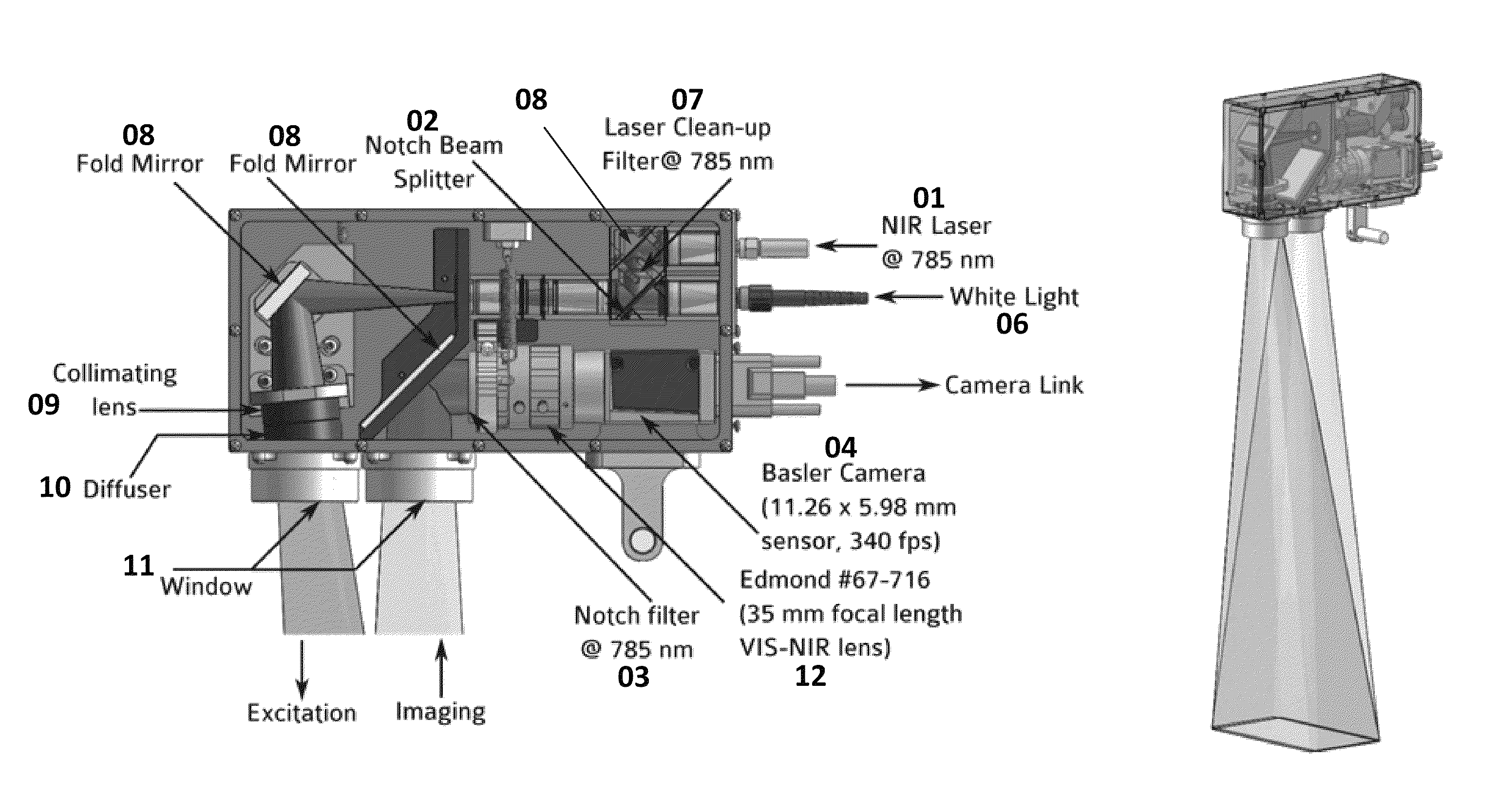
[0168]By removing the NIR short pass filter in front of the sensor, it is possible to detect fluorescence light emitted by the NIR fluorophores on all RGB channels (FIG. 2). But in order to differentiate between the visible light and NIR light we have to ensure that there is no visible light on the sensor when capturing an NIR image frame. In order to capture the NIR light, there should not be any visible light. In some situations, we capture one frame when there is no visible light or NIR light, record the light, and then subtract it from the NIR captured frame. A clinical prototype is shown in FIGS. 6A-6C.

1. Filter Combination:

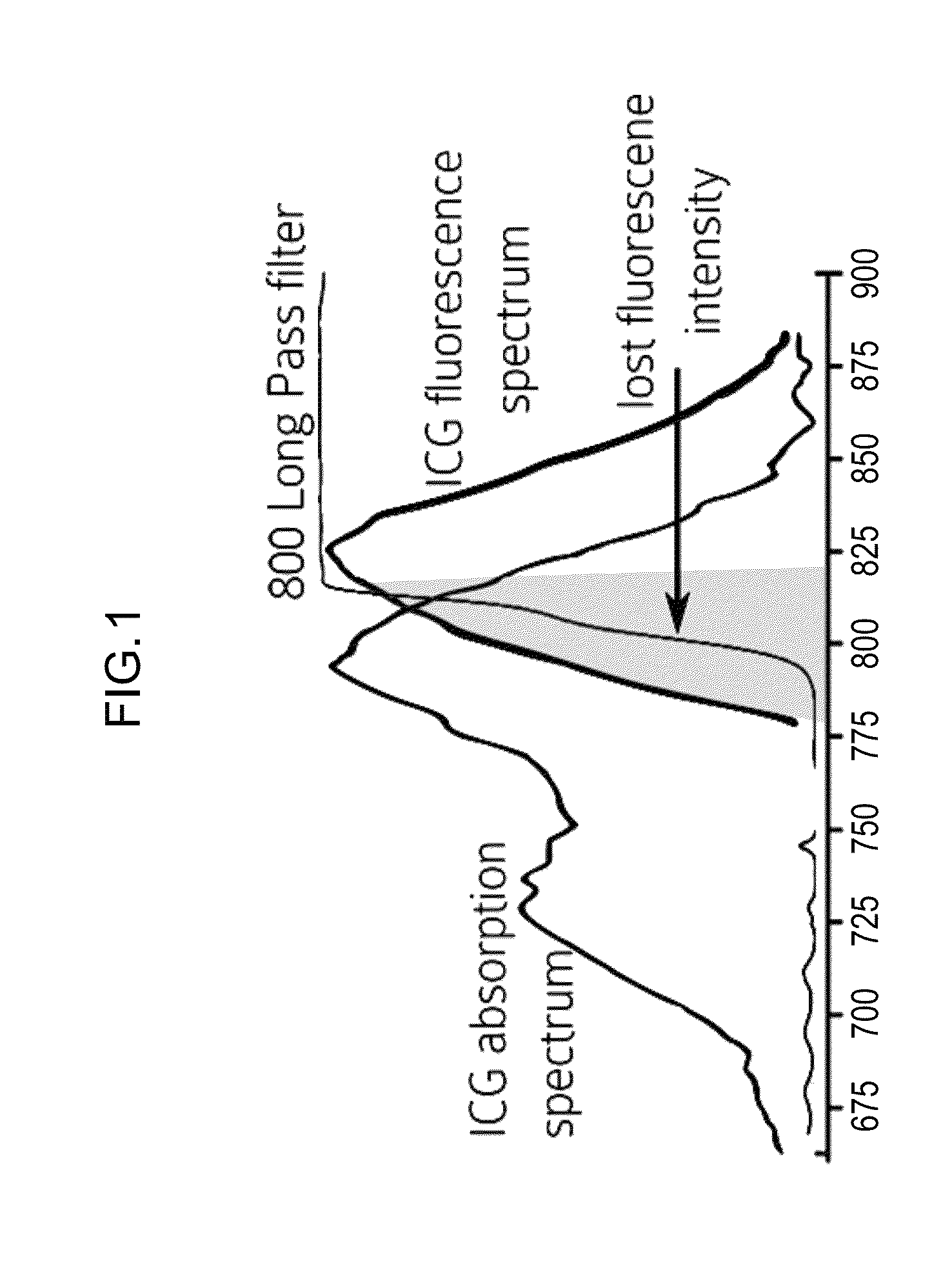
[0169]We use a very specific filter combination to achieve highest signal to noise ratio (SNR). Instead of using a broadband excitation as described in most current NIR system, we use an extremely narrow band excitation at 785 nm (optimal for ICG, may vary depending on the fluorophore), the excitation is further narrowed using a laser clean up filter (FIG. 7...


PUM


Abstract

The invention provides systems and methods for imaging a sample. In various embodiments, the invention provides a system comprising an image sensor, a laser for emitting excitation light for an infrared or near-infrared fluorophore, a visible light source, a notch beam splitter, a notch filter, a synchronization module, an image processing unit, an image displaying unit, and light-conducting channels. In various embodiments, the present invention provides a system comprising an image sensor, a laser for emitting excitation light for an infrared or near-infrared fluorophore, a laser clean-up filter, a notch filter, a white light source, an image processing unit, an image displaying unit, and light-conducting channels. In accordance with the present invention, the image sensor can detect both visible light and infrared light.

Description

CROSS-REFERENCE TO RELATED APPLICATIONS[0001]This application is a continuation-in-part of International Patent Application No. PCT / US2014 / 035203, filed Apr. 23, 2014, which designated the U.S., was published under PCT Article 21(2) in English, and claims priority under 35 U.S.C. §119(e) to U.S. provisional patent application No. 61 / 814,955, filed Apr. 23, 2013. This application also claims priority under 35 U.S.C. §119(e) to U.S. provisional patent application No. 62 / 049,312, filed Sep. 11, 2014. The contents of all the related applications cross-referenced herein are herein incorporated by reference in their entirety as though fully set forth.FIELD OF INVENTION[0002]The invention provides systems and methods for recording simultaneously visible light image and infrared (IR) light image from fluorophores.BACKGROUND OF THE INVENTION[0003]All publications cited herein are incorporated by reference in their entirety to the same extent as if each individual publication or patent applic...

Claims


Application Information

Patent Timeline
Patent Type & Authority Patents(United States)
IPC IPC(8): H04N5/33G01J1/04H04N5/225A61B1/04G01J1/44H04N5/235G01J3/44A61B1/07A61B1/06A61B1/00
CPCH04N5/332G01J1/0414G01J1/44H04N5/2354H04N5/2256H04N5/2252A61B1/043A61B1/00117A61B1/063A61B1/0646A61B1/00009A61B1/00045A61B1/07G01J3/44G01J2001/448A61B1/00186A61B1/00188A61B1/042A61B1/05A61B1/0638A61B1/0669H04N23/10H04N23/11H04N23/51H04N23/56H04N23/74G01N21/6456G01N2021/6463G06T7/0012H04N5/33
Inventor BUTTE, PRAMODMAMELAK, ADAM
Owner CEDARS SINAI MEDICAL CENT
Why Eureka
Try Eureka