Handle structure and electronic apparatus having same handle structure

a technology of electronic devices and handles, applied in the direction of electric apparatus casings/cabinets/drawers, instruments, casings with display/control units, etc., to achieve the effect of convenient holding of users, saving packaging, and placing space without affecting the integral beauty of electronic devices

Active Publication Date: 2016-08-02
WISTRON CORP
View PDF31 Cites 6 Cited by
  • Summary
  • Abstract
  • Description
  • Claims
  • Application Information

AI Technical Summary

Benefits of technology

[0011]To sum up, for a handle structure and an electronic apparatus according to an embodiment of the present invention, a first cover body of the handle structure is rotatably connected to a receiving groove of a housing to adjust a use angle of the electronic apparatus, so that the handle structure is used as a foot of the electronic apparatus; and a sliding member of the handle structure is slidably combined with the first cover body or a second cover body to drive the handle member to slide, so that the handle structure is used as an extensible handle of the electronic apparatus and facilitates holding of a user, thereby saving packaging and placing space without affecting integral beauty of the appearance of the electronic apparatus.

Problems solved by technology

However, the design of a handle structure of a conventional AIO PC may cause inconvenient packaging and placing of the entire machine of the AIO PC, and affect integral beauty of the appearance of the AIO PC.
Therefore, how to design a handle structure of an electronic apparatus that can facilitate holding of a user, and save overall package and placing space of the electronic apparatus without affecting integral beauty of the appearance of the electronic apparatus becomes an important issue to be figured out by a person skilled in the art.

Method used


Image

  • Handle structure and electronic apparatus having same handle structure
  • Handle structure and electronic apparatus having same handle structure
  • Handle structure and electronic apparatus having same handle structure

Examples


Embodiment Construction

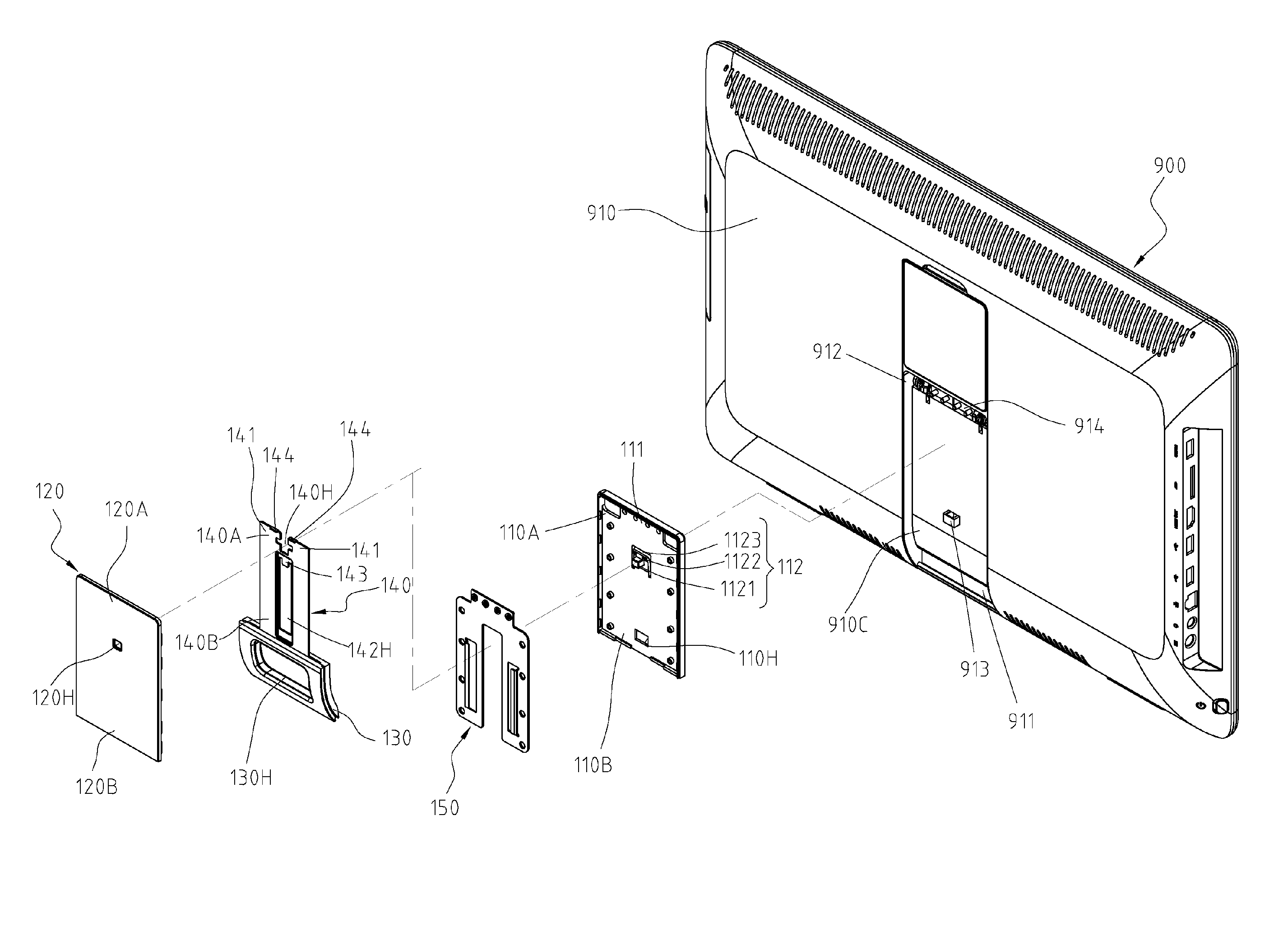
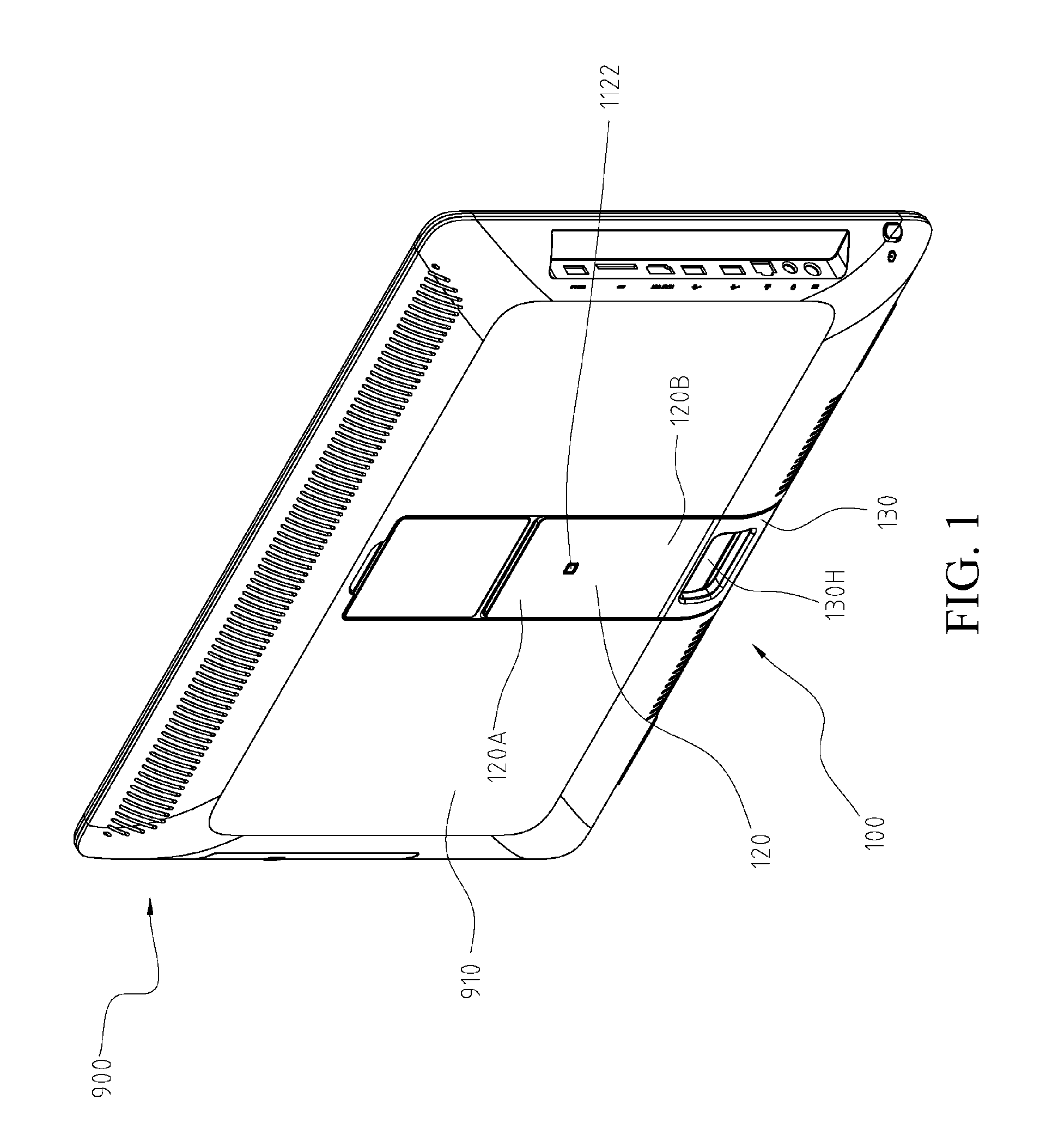
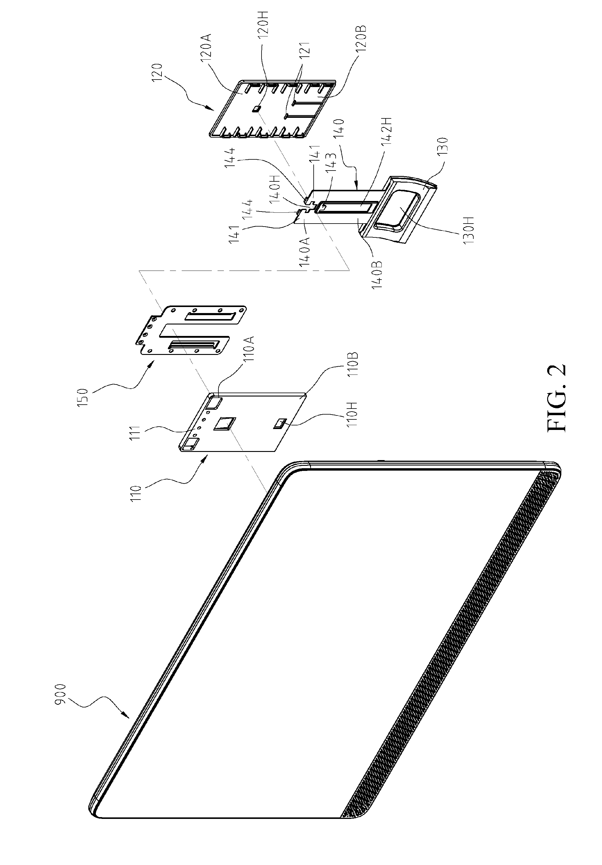
[0023]Refer to FIG. 1 to FIG. 5, which are a schematic outline overview of illustrating that a handle structure is installed in an electronic apparatus according to an embodiment of the present invention, a three-dimensional exploded view (1) of a handle structure, a three-dimensional exploded view (2) of a handle structure, a partial enlarged schematic view of a positioning portion of a handle structure, and a schematic overview illustrating that a sliding member of a handle structure is in an accommodating position, respectively, disclosing a handle structure 100 applicable to an electronic apparatus 900. The electronic apparatus 900 includes a housing 910, and the housing 910 is provided with a receiving groove 910C. For convenience of description, one end, which is open and adjacent to a side edge of the housing 910, and the other end, which is closed and located at the inner side of the housing 910, of the receiving groove 910C are indicated by a first end 911 and a second end ...


PUM


Abstract

A handle structure and an electronic apparatus having the handle structure are provided. A housing of the electronic apparatus has a receiving groove adjacent to one side of the electronic apparatus. The handle structure is pivotally connected to the receiving groove and can be moved opposite to the housing, so as to form a foot mode and a handle mode. In the foot mode, a sliding member of the handle structure is in an accommodating position, and a second end can be locked with a positioning portion in a locking position. When the positioning portion is in a release position, a second end of a sliding member can be detached from the positioning portion and slid to a stretch position, making a handle member exposed out of the receiving groove to form the handle mode.

Description

CROSS-REFERENCES TO RELATED APPLICATIONS[0001]This non-provisional application claims priority under 35 U.S.C. §119(a) on Patent Application No. 201510028445.5 filed in China, P.R.C. on Jan. 20, 2015, the entire contents of which are hereby incorporated by reference.BACKGROUND[0002]1. Technical Field[0003]The present invention provides a handle structure, and in particular, to a handle structure that is applicable to an electronic apparatus, and optionally supports the electronic apparatus as a foot.[0004]2. Related Art[0005]As the Information Age approaches, computer products, communications products, and consumer electronic products have become one of the fast growing industries in the world. Herein, the computer products are quite widely applied, ranging from use in working, daily life, or entertainment, to the like, and have become one of the essential articles in the life of modern people.[0006]With the development of science and technology and the emerging of the concept of in...

Claims


Application Information

Patent Timeline
Patent Type & Authority Patents(United States)
IPC IPC(8): G06F1/16H05K5/00H05K5/02
CPCH05K5/023H05K5/0234H05K5/0017F16M11/046F16M11/10F16M11/16F16M13/04G06F1/16G06F1/1601G06F1/1626G06F2200/1612G06F2200/1631
Inventor LUO, XIREN
Owner WISTRON CORP
Why Eureka
Try Eureka