
A fast-installation corner code for profile frame doors and windows and its application method

A corner code and profile technology, applied in the direction of windows/doors, building components, buildings, etc., can solve the problems of increasing production, storage and transportation, construction period and cost, high labor intensity, inconvenient installation, etc., to shorten the installation or maintenance. The effect of cycle, saving materials and man-hours, and convenient installation

Active Publication Date: 2018-06-01
SHANDONG JUNQIANGBONA HARDWARE TECH CO LTD
View PDF5 Cites 0 Cited by
  • Summary
  • Abstract
  • Description
  • Claims
  • Application Information

AI Technical Summary

Problems solved by technology

However, most of the existing corner codes still have some shortcomings: the structure is relatively complicated, the installation is inconvenient, easy to loosen, and the firmness is poor
In particular, it is generally installed in the factory, and the overall shipment, transportation, and movement of doors and windows are difficult, expensive, and labor-intensive.
Moreover, it is fragile, which greatly increases the time limit and cost of production, storage, transportation and construction.

Method used


Image

  • A fast-installation corner code for profile frame doors and windows and its application method
  • A fast-installation corner code for profile frame doors and windows and its application method
  • A fast-installation corner code for profile frame doors and windows and its application method

Examples


Embodiment Construction

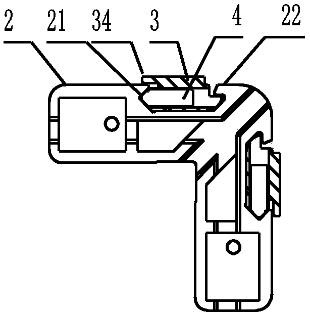
[0027] The present invention is described below in conjunction with accompanying drawing and embodiment: Embodiment: referring to accompanying drawing, a kind of firm quick-loading corner code of profile frame door and window is provided with corner code body and fixing part, and described corner code body 2 is a kind of right angle Shape, on the side of two right-angled sides, be respectively provided with a fixing member installation hole, each fixing member installation hole is provided with a fixing member 3, the shape and size of each fixing member are just in line with the corresponding fixing member installing hole match; a threaded screw hole 4 is provided at the bottom of the fixing piece, and a fastening screw is arranged in the screw hole; the outer wall of each fixing piece mounting hole is the right-angled side wall of the corner code body There is a screw mounting hole 5 for installing the fastening screw, the inner end of the screw mounting hole is opposite to th...


PUM


Abstract

The invention relates to a firm quick mounting corner connector of a profile frame door and window. The firm quick mounting corner connector comprises a corner connector body and fixing parts and is characterized in that the corner connector body is in a right angle shape, the side faces of two right angle edges are each provided with a fixing part mounting hole, the fixing parts are arranged in the mounting holes, and the shape and size of each fixing part are exactly matched with those of the corresponding fixing part mounting hole; a screw hole with an internal thread is formed in the lower portion of each fixing part, and a fastening screw is arranged in each screw hole; a screw mounting hole for allowing the corresponding fastening screw to be mounted is formed in the side wall close to the right angle of the corner connector body, namely, the outer wall of each fixing part mounting hole, the inner end of each screw mounting hole is opposite to the outer end of the corresponding fastening screw, the outer end of each screw mounting hole is directly communicated with the outside of the other side face of the corner connector body, and a mounting tool screwdriver for the fastening screws can pass through the mounting holes to rotate the fastening screws. The firm quick mounting corner connector is suitable for corner connection of frames and sashes of the door and window, novel in structure and convenient to use, corner connection of the frames and sashes of the door and window are very firm, assembly is convenient and fast, the service life is prolonged, and repair and maintenance are reduced.

Description

technical field [0001] The invention relates to the technical field of architectural profile door and window hardware accessories, in particular to a corner bracket for a profile door and window frame, a completely new type of corner bracket. The door and window frames can be installed together very simply and quickly, which is not only simple and fast, but also very firm. The doors and windows can be completely assembled on site, greatly reducing the cost of transportation and installation, and improving work efficiency. It is suitable for corner installation of various profile doors and windows. Background technique [0002] The group corner codes of existing door and window frames are various, and along with the progress of technology, some novel products constantly appear. These product structures are not the same, each with its own characteristics. But most of the existing corner codes still have some deficiencies: relatively complicated structure, inconvenient insta...

Claims


Application Information

Patent Timeline
Patent Type & Authority Patents(China)
IPC IPC(8): E06B3/964
CPCE06B3/964
Inventor 化明杰李俊英李洪斌郭淑静化风强
Owner SHANDONG JUNQIANGBONA HARDWARE TECH CO LTD
Learn More