Helicopter with cross-flow fan

a cross-flow fan and helicopter technology, applied in the field of helicopters, can solve the problems of affecting the performance of the helicopter, the ability to damage the open tail rotor, and the inability to fully achieve the minimum drag fuselage attitude, etc., and achieve the effect of improving performan

Active Publication Date: 2016-08-09
AIRBUS HELICOPTERS DEUT GMBH
View PDF11 Cites 26 Cited by
  • Summary
  • Abstract
  • Description
  • Claims
  • Application Information

AI Technical Summary

Benefits of technology

[0022]According to an advantage of the invention the cross-flow fan provides first of all anti-torque for the helicopter as a consequence of the angular offset of the separate gaps in the housing for said air inlet and for said air outlet. Said angular offset preferably varies from 10° to 90° for an angle measured between a side from the fan axis to a lateral inlet delimitation of the inlet and a side to a lateral outlet delimitation of the outlet next to said lateral inlet delimitation of the inlet. Said cross-flow fan is characterized by one dominant dimension, namely relative to the overall dimensions of the helicopter small in diameter, while as long as needed.
[0023]Any fluid, e.g. air, entering the cross-flow fan at the inlet passes crosswise to the fan axis along the radial oriented airfoil blades towards the outlet, providing two consecutive compressions, one after the fluid having entered and another one after having left the ring. The inventive cross-flow fan comprises the compressor, rotating around its fan axis and the special housing built in close contact around the radial outer tips of the airfoil blades of the compressor. The housing in close contact with the radial outer tips of the airfoil blades of the compressor prevents the fluid from trespassing radially the airfoil blades not in line with either the inlet or the outlet.
[0024]The compressor comprises the given number of small aerodynamically shaped airfoil blades, spaced relative to each other in the azimuth direction from the yaw axis. Contrary to classical tail rotors of helicopters creating anti-torque for compensation of the fuselage and the main rotor torque by creating an essentially lateral force, the inventive helicopter with a cross-flow fan allows provision of anti-torque without tail rotor. Further contrary to classical tail rotors of helicopters needing horizontal stabilizers creating forces in the direction of the yaw axis, e.g. negative lift, to balance the fuselage pitch and a vertical fin creating lateral forces perpendicular to a plane of said roll axis and said yaw axis without any further support of helicopter flight performance generally, the inventive helicopter with a cross-flow fan provides support of helicopter flight performance in general. The provision and the arrangement of the cross-flow fan of the inventive helicopter improve performance in several ways, namely by providing:
[0027]A combination of said anti-torque and said lift device, i.e. both lateral and vertical thrust direction;
[0028]Additional thrust due to the so called “Coanda effect” resulting outside the housing; and / or
[0029]Additional thrust due to a diffusor type air outlet of the housing;

Problems solved by technology

Therefore, the minimum drag fuselage attitude might not be fully achieved.
Fixed vertical and horizontal stabilizing surfaces do not provide any additional propulsive force;
Open tail-rotors are a potential danger for humans and can be damaged by foreign objects;
The rotating devices cannot be easily changed in diameter without having major changes and re-designs of the entire helicopter.

Method used


Image

  • Helicopter with cross-flow fan
  • Helicopter with cross-flow fan
  • Helicopter with cross-flow fan

Examples


Embodiment Construction

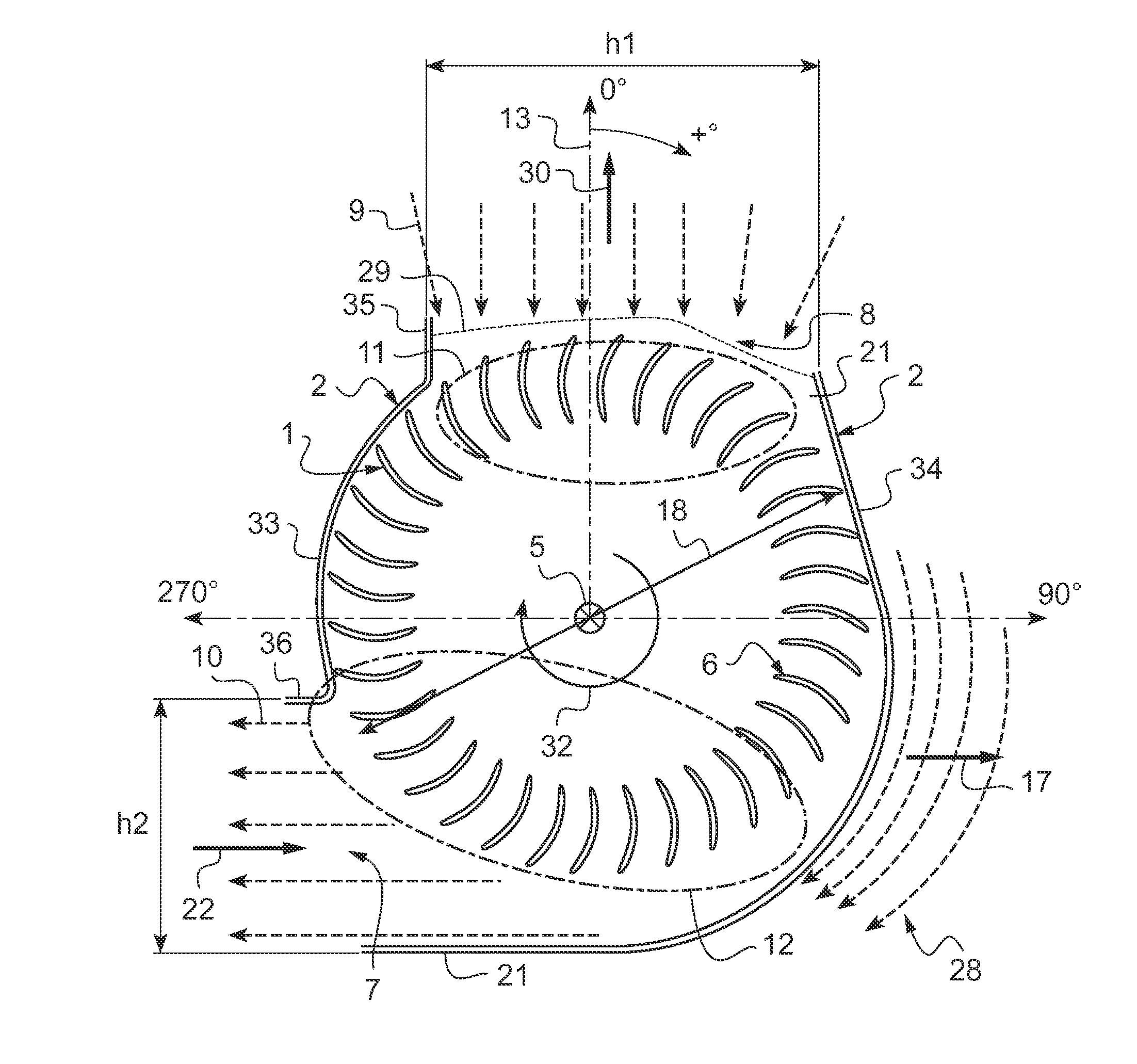
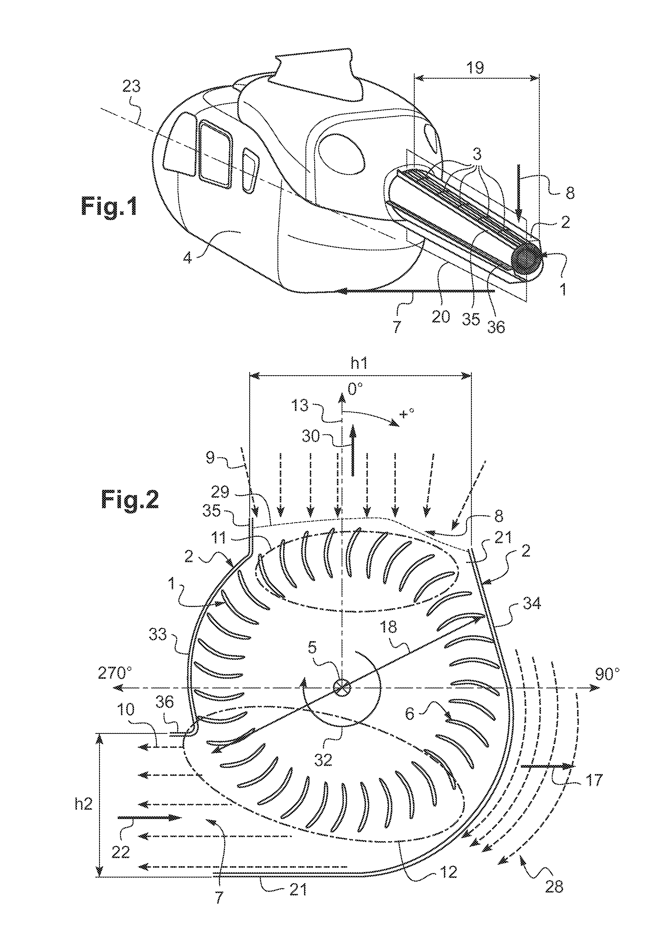
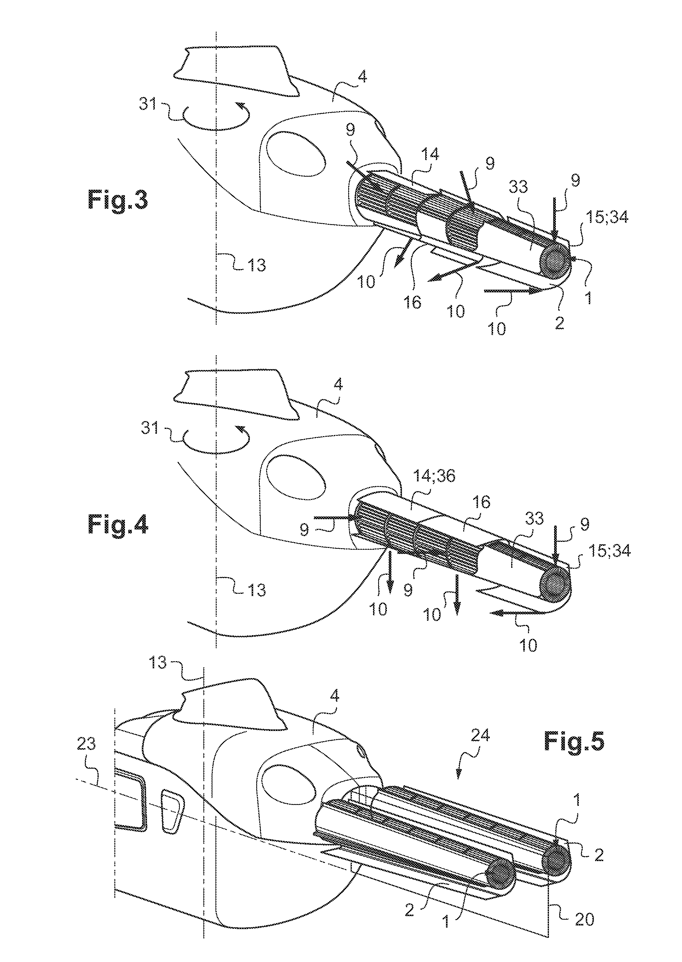
[0051]According to FIG. 1, a helicopter comprises a fuselage 4 with at least one driving unit, e.g. an integrated engine (not shown). The at least one integrated engine drives a main rotor (not shown) via a main gear box (not shown) mounted on top of the fuselage 4 of the helicopter. A rotation axis of the main rotor corresponds to a yaw axis 13 (see FIG. 3) of the helicopter.

[0052]A housing 2 of a cross flow fan is mounted to an aft region of said fuselage 4 with a roll axis 23 perpendicular to said yaw axis 13. Said housing 2 extends with angular variations of up to + / −15° relative to said yaw axis 13 essentially in direction of a roll axis 23 of the helicopter with an offset defined by a longitudinal extension 19 of the compressor 1 and housing 2 in direction of said roll axis 23 relative to said yaw axis 13.

[0053]A helicopter width is defined as the maximum distance between respective left hand and right hand surfaces of the fuselage 4 measured orthogonally to a helicopter mid-p...


PUM


Abstract

A helicopter with a fuselage (4), at least one engine, a roll axis, at least one main rotor, and at least one housing (2) mounted to said fuselage (4). An air inlet (8) and an air outlet (7) are provided along at least a part of a circumference of the at least one housing (2), said air inlet (8) and said air outlet (7) being formed by angularly offset and separate gaps between an inside segment (33) and an outside segment (34) essentially extending respectively longitudinally in direction of said roll axis. At least one rotatable compressor (1) with a plurality of airfoil blades (6) is provided radial inside said at least one housing (2) between said air inlet (8) and said air outlet (7), said at least one rotatable compressor (1) being drivable by said at least one engine about a fan axis (5) and each chord of said airfoil blades (6) is essentially radial oriented with regard to said fan axis (5).

Description

CROSS REFERENCE TO RELATED APPLICATION[0001]This application claims priority to European patent application No. EP 13 400011.6 filed May 30, 2013, the disclosure of which is incorporated in its entirety by reference herein.BACKGROUND OF THE INVENTION[0002](1) Field of the Invention[0003]The invention relates to helicopters and particularly to helicopters with an anti-torque device according to the preamble of claim 1.[0004](2) Description of Related Art[0005]A configuration of a current rotary wing flying machine, e.g. a helicopter, comprises a main rotor, which in operation transmits a torque around a yaw axis of the helicopter. In operation this torque is countered by an empennage with typically an anti-torque device, such as a tail rotor, a shrouded tail rotor, i.e. a so called Fenestron, and a vertical fin. Exception made for the fin, all other anti-torque devices need power in order to provide this anti-torque needed for a helicopter operating properly.[0006]Additionally a typi...

Claims


Application Information

Patent Timeline
Patent Type & Authority Patents(United States)
IPC IPC(8): B64C27/82B64C27/06
CPCB64C27/06B64C27/82B64C2027/8245
Inventor MORES, SEBASTIAND'ALASCIO, ALESSANDROBEBESEL, MARIUS
Owner AIRBUS HELICOPTERS DEUT GMBH
Why Eureka
Try Eureka