Cable with LED connection indicator and methods of using same

a technology of led connection indicator and led connection, which is applied in the direction of coupling device connection, force measurement, instruments, etc., can solve the problems of pe material deformation, unwanted electrons manufactured from external electrical fields, and costly and challenging methods of verifying interconnections between cabling and a plurality of devices

Inactive Publication Date: 2016-08-09
PCB PIEZOTRONICS OF NORTH CAROLINA
View PDF13 Cites 2 Cited by
  • Summary
  • Abstract
  • Description
  • Claims
  • Application Information

AI Technical Summary

Benefits of technology

[0014]Another object of the present patent document is to provide an interconnection verification between cabling and sensors in multi-channel test configurations. A further object of the present patent document is to provide a means to ease interconnection verification between a receiving amplifier and its associated IEPE sensor in multi-channel test configurations using the existing 2-wire IEPE cabling interface. Yet another object of the present patent document is to provide a device or means that can be used to remotely alert and communicate diagnostic feedback, functional failings, and / or improper operational conditions information.

Problems solved by technology

There are costly and challenging methods of verifying interconnections between cabling and a plurality of devices, including but not limited to sensors and the like.
When the mounting surface that the base is attached to is accelerated, the inertial mass is also accelerated and results in a force that causes the PE material to deform.
One problem that needs to be overcome in the design of detectors is the shielding from unwanted electrons that can be induced from myriad of external sources.
For example, unwanted electrons may be manufactured from external electrical fields or from the rubbing of insulators in the electrical wires delivering the output to the data acquisition system.
Again, if the cable is wired to the sensing equipment incorrectly, the readings will be corrupted.
All of this creates a verification nightmare.

Method used


Image

  • Cable with LED connection indicator and methods of using same
  • Cable with LED connection indicator and methods of using same
  • Cable with LED connection indicator and methods of using same

Examples


Embodiment Construction

[0034]The terms “computer-readable storage medium” and “computer-readable storage media,” as used herein, refer to a medium or media that participates in providing instructions to a CPU for execution. Such media may take many forms that include, but are not limited to, non-volatile and volatile media. Non-volatile media include optical or magnetic disks, such as fixed disks. Volatile media include dynamic memory, such as system RAM. Common forms of computer-readable storage media include, for example, floppy disks, flexible disks, hard disks, magnetic tape, any other magnetic media, CD-ROM disks, digital video disks (DVDs), any other optical media, punch cards, paper tape, any other physical media with patterns of marks or holes, RAM, PROM, EPROM, FLASHEPROM, and any other memory chip or cartridge.

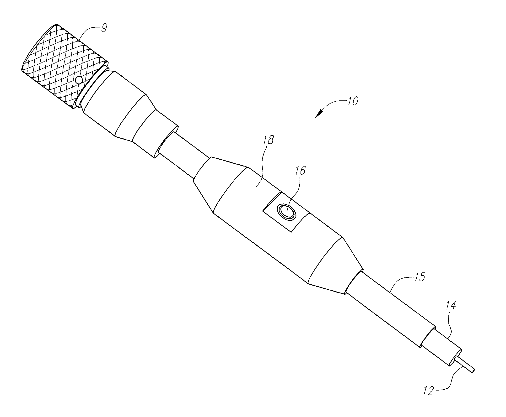
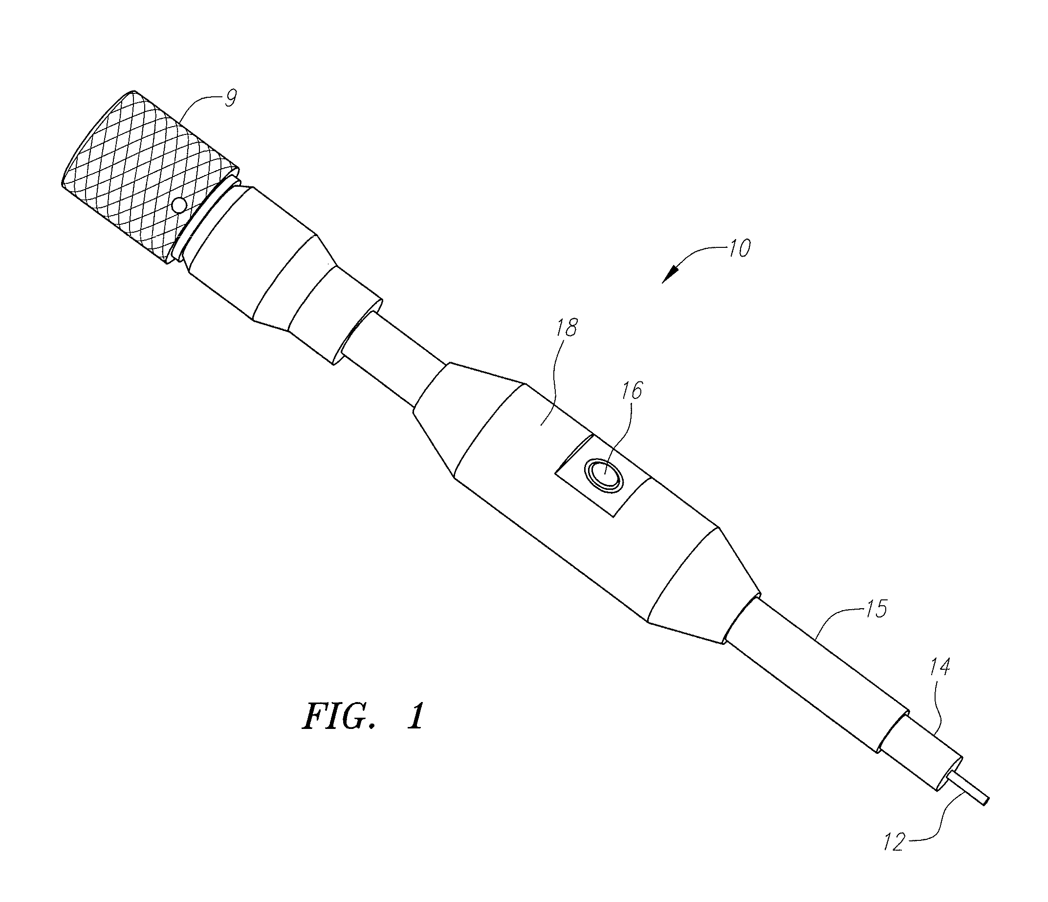
[0035]FIG. 1 illustrates an isometric view of one embodiment of a sensor cable assembly 10 including a mating sensor connector 9 and an indicator assembly 18 with an indicator 16 designed ...


PUM


Abstract

An interconnection verification device for sensors and a software implementation of interconnection verification between cabling and sensors in large, multi-channel test configurations are disclosed. In a preferred embodiment the sensor assembly comprises a sensor and an indicator electrically connected inline with the sensor. In a preferred embodiment the indicator is an LED. In an even more preferred embodiment, the sensor is an IEPE.

Description

RELATED APPLICATIONS[0001]This application claims the benefit of U.S. Provisional Patent Application No. 61 / 758,850, filed Jan. 31, 2013, and entitled “LED Cable End Identifier,” and U.S. Provisional Patent Application No. 61 / 807,018, filed Apr. 1, 2013, and entitled “LED Cable End Identifier Software,” both of which are incorporated herein by reference.FIELD[0002]The present patent document relates generally to cables with light emitting diodes (LED) incorporated therein to indicate the status, location or health of a connected component. The present patent document further relates to software implementations of a connection indicator, and more particularly to an interconnection verification between cabling and sensors in large, multi-channel test configurations.BACKGROUND[0003]There are costly and challenging methods of verifying interconnections between cabling and a plurality of devices, including but not limited to sensors and the like. Dynamic sensors are transducers that are ...

Claims


Application Information

Patent Timeline
Patent Type & Authority Patents(United States)
IPC IPC(8): G08B5/22G08B21/18H01R13/641H01R13/717G01R5/28G01R13/00G01R31/28G01D3/08
CPCG01R5/28H01R13/7175H01R13/641G08B21/18G01R31/026G08B21/185G01D3/08G01R13/00G01R31/2829G01L1/16G01L1/26
Inventor ZAVIS, WAYNE
Owner PCB PIEZOTRONICS OF NORTH CAROLINA
Why Eureka
Try Eureka