Methods for driving electro-optic displays

a technology of electrooptic displays and displays, applied in optics, static indicating devices, instruments, etc., can solve problems such as preventing their widespread use, inadequate service life of these displays, and error in writing images on impulse-driven displays

Inactive Publication Date: 2016-08-09
E INK CORPORATION
View PDF244 Cites 151 Cited by
  • Summary
  • Abstract
  • Description
  • Claims
  • Application Information

AI Technical Summary

Problems solved by technology

Nevertheless, problems with the long-term image quality of these displays have prevented their widespread usage.
For example, particles that make up electrophoretic displays tend to settle, resulting in inadequate service-life for these displays.
However, inevitably there is some error in writing images on an impulse-driven display.
(a) Prior State Dependence; With at least some electro-optic media, the impulse required to switch a pixel to a new optical state depends not only on the current and desired optical state, but also on the previous optical states of the pixel.
(b) Dwell Time Dependence; With at least some electro-optic media, the impulse required to switch a pixel to a new optical state depends on the time that the pixel has spent in its various optical states. The precise nature of this dependence is not well understood, but in general, more impulse is required that longer the pixel has been in its current optical state.
(c) Temperature Dependence; The impulse required to switch a pixel to a new optical state depends heavily on temperature.
(d) Humidity Dependence; The impulse required to switch a pixel to a new optical state depends, with at least some types of electro-optic media, on the ambient humidity.
(e) Mechanical Uniformity; The impulse required to switch a pixel to a new optical state may be affected by mechanical variations in the display, for example variations in the thickness of an electro-optic medium or an associated lamination adhesive. Other types of mechanical non-uniformity may arise from inevitable variations between different manufacturing batches of medium, manufacturing tolerances and materials variations.
(f) Voltage Errors; The actual impulse applied to a pixel will inevitably differ slightly from that theoretically applied because of unavoidable slight errors in the voltages delivered by drivers.
General grayscale image flow suffers from an “accumulation of errors” phenomenon.
This accumulation of errors phenomenon applies not only to errors due to temperature, but also to errors of all the types listed above.
As described in the aforementioned 2003 / 0137521, compensating for such errors is possible, but only to a limited degree of precision.
For example, temperature errors can be compensated by using a temperature sensor and a lookup table, but the temperature sensor has a limited resolution and may read a temperature slightly different from that of the electro-optic medium.
Similarly, prior state dependence can be compensated by storing the prior states and using a multi-dimensional transition matrix, but controller memory limits the number of states that can be recorded and the size of the transition matrix that can be stored, placing a limit on the precision of this type of compensation.
Such a slide show drive scheme produces accurate grayscale levels, but the flashing of the display as it is driven to the optical rails is distracting to the viewer.
However, this type of “limited slide show” drive scheme is, if anything, even more distracting to the viewer, since the solid flashing of a normal slide show drive scheme is replaced by image dependent flashing, in which features of the old image and the new image flash in reverse color on the screen before the new image is written.
Obviously, a pure general grayscale image flow drive scheme cannot rely upon using the optical rails to prevent errors in gray levels since in such a drive scheme any given pixel can undergo an infinitely large number of changes in gray level without ever touching either optical rail.
However, during the scanning of an active matrix display using such pulse width modulation, conventional driver circuitry only allows one to apply a single voltage to any given pixel during any one scan of the matrix.
Frames of this length lead to difficulties in fine control of gray scale with many fast switching electro-optic medium.
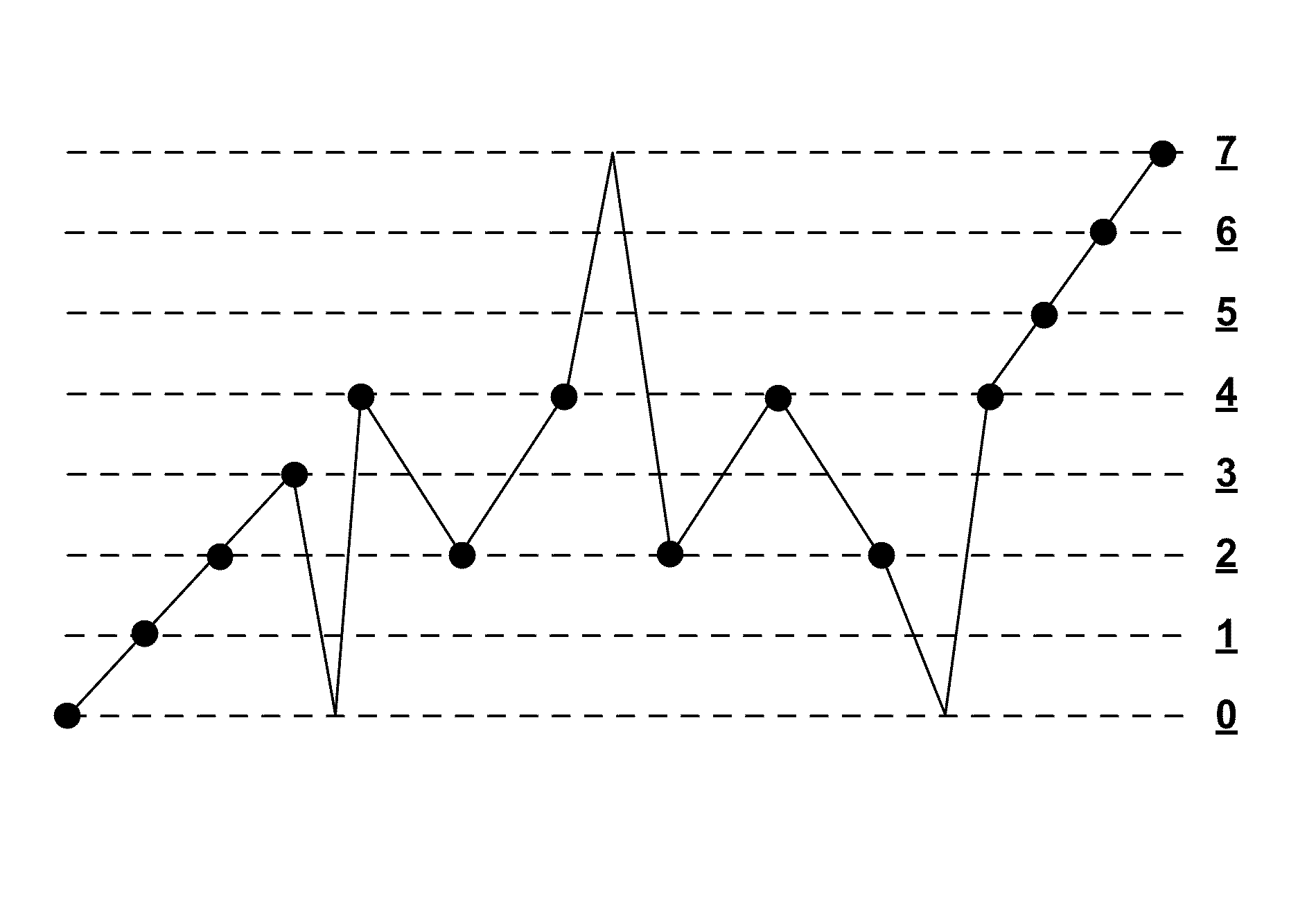
Such a shift is too large for accurate control of gray scale; the human eye is sensitive to differences in gray levels of about 1 L* unit, and controlling the impulse only in graduations equivalent to about 6 L* units is likely to give rise to visible artifacts, such as “ghosting” due to prior state dependence of the electro-optic medium, and pulses needed to ensure that the waveform used is DC balanced (see the applications mentioned in the “Cross Reference to Related Applications” section above).
For example, in a simple 4 gray level (2 bit) display having gray levels 0 (black), 1 (dark gray), 2 (light gray) and 3 (white), driven by a simple pulse width modulation drive scheme, these non-linearities may result in the actual gray level achieved after a notional 0-2 transition being different from the gray level achieved after a notional 1-2 transition, with the production of highly undesirable visual artifacts.

Method used


Image

  • Methods for driving electro-optic displays
  • Methods for driving electro-optic displays
  • Methods for driving electro-optic displays

Examples


example

Use of FT Sequences in Cyclic RSGS Waveform

[0396]This Example illustrates the use of FT sequences in improving the optical performance of a waveform designed at achieve 4 gray level (2-bit) addressing of a single pixel display. This display used an encapsulated electrophoretic medium and was constructed substantially as described in Paragraphs [0069] to [0076] of the aforementioned 2002 / 0180687. The single-pixel display was monitored by a photodiode.

[0397]Waveform voltages were applied to the pixel according to a transition matrix (look-up table), in order to achieve a sequence of gray levels within the 2-bit (4-state) grayscale. As already explained, a transition matrix or look-up table is simply a set of rules for applying voltages to the pixel in order to make a transition from one gray level to another within the gray scale.

[0398]The waveform was subject to voltage and timing constraints. Only three voltage levels, −15V, 0V and +15V were applied across the pixel. Also, in order ...


PUM


Abstract

An electro-optic display, having at least one pixel capable of achieving any one of at least four different gray levels including two extreme optical states, is driven by displaying a first image on the display, and rewriting the display to display a second image thereon, wherein, during the rewriting of the display, any pixel which has undergone a number of transitions exceeding a predetermined value without touching an extreme optical state, is driven to at least one extreme optical state before driving that pixel to its final optical state in the second image.

Description

REFERENCE TO RELATED APPLICATIONS[0001]This application is a divisional of application Ser. No. 10 / 879,335, filed Jun. 24, 2004 (Publication No. 2005 / 0024353, now U.S. Pat. No. 7,528,822), which claims benefit of the following Provisional Applications: (a) Ser. No. 60 / 481,040, filed Jun. 30, 2003; (b) Ser. No. 60 / 481,053, filed Jul. 2, 2003; and (c) Ser. No. 60 / 481,405, filed Sep. 22, 2003.[0002]The aforementioned application Ser. No. 10 / 879,335 is also a continuation-in-part of application Ser. No. 10 / 814,205, filed Mar. 31, 2004 (Publication No. 2005 / 0001812, now U.S. Pat. No. 7,119,772), which itself claims benefit of the following Provisional Applications: (d) Ser. No. 60 / 320,070, filed Mar. 31, 2003; (e) Ser. No. 60 / 320,207, filed May 5, 2003; (f) Ser. No. 60 / 481,669, filed Nov. 19, 2003; (g) Ser. No. 60 / 481,675, filed Nov. 20, 2003; and (h) Ser. No. 60 / 557,094, filed Mar. 26, 2004.[0003]The aforementioned copending application Ser. No. 10 / 814,205 is also a continuation-in-part...

Claims


Application Information

Patent Timeline
Patent Type & Authority Patents(United States)
IPC IPC(8): G09G3/34G02F1/167G09G5/00
CPCG09G3/344G02F1/167G02F1/1681G09G3/2018G09G2300/0426G09G2310/0254G09G2310/061G09G2310/08G09G2320/0271G09G2330/021G09G2360/18
Inventor AMUNDSON, KARL R.ZEHNER, ROBERT W.KNAIAN, ARA N.ZION, BENJAMIN
Owner E INK CORPORATION
Why Eureka
Try Eureka