Inkjet printer

a technology of inkjet printer and inkjet paper, which is applied in the direction of printing, other printing apparatus, etc., can solve the problems of reducing the adsorption power of the medium adsorbing device, generating ink mist, and being more difficult to achieve, so as to reduce the effective range of adsorption power, suppress adsorption power, and reduce the effect of wrinkles

Active Publication Date: 2016-08-30
MIMAKI ENG
View PDF5 Cites 1 Cited by
  • Summary
  • Abstract
  • Description
  • Claims
  • Application Information

AI Technical Summary

Benefits of technology

[0020]According to this configuration, since the mesh-like conveyance belt is disposed between the medium adsorbing unit and a media, the inkjet printer of the disclosure can broaden the effective range of adsorption power which is generated from the suction holes of the medium adsorbing unit, according to the internal space of the mesh-like conveyance belt. For this reason, the inkjet printer of the disclosure can suppress adsorption power from extremely changing at the boundaries between the individual sections of the medium adsorbing unit. Therefore, the inkjet printer of the disclosure can suppress wrinkles from being formed in media at the boundaries between the individual sections of the medium adsorbing unit while the media are conveyed.
[0021]The inkjet printer of the disclosure can suppress a reduction in adsorption power relative to media as compared to the related art.

Problems solved by technology

However, in the inkjet printer disclosed in Patent Document 1, adsorption power in the downstream side adjacent section is higher than adsorption power in the printing section, and thus it is likely that ink mist generated by printing of the inkjet head on media is sucked from the suction holes of the downstream side adjacent section.
Therefore, the inkjet printer disclosed in Patent Document 1 has a problem that the inside of the medium adsorbing device is clogged by the sucked ink, resulting in a reduction in the adsorption power of the medium adsorbing device.
According to this configuration, in the inkjet printer of the disclosure, since adsorption power in the downstream side adjacent section is equal to or lower than adsorption power in the printing section, as compared to the related art, it is more difficult that ink mist generated by printing of the inkjet head on media is sucked by the suction holes of the downstream side adjacent section.

Method used


Image

  • Inkjet printer
  • Inkjet printer
  • Inkjet printer

Examples


first embodiment

[0039]First, the configuration of an inkjet printer according to the first embodiment will be described.

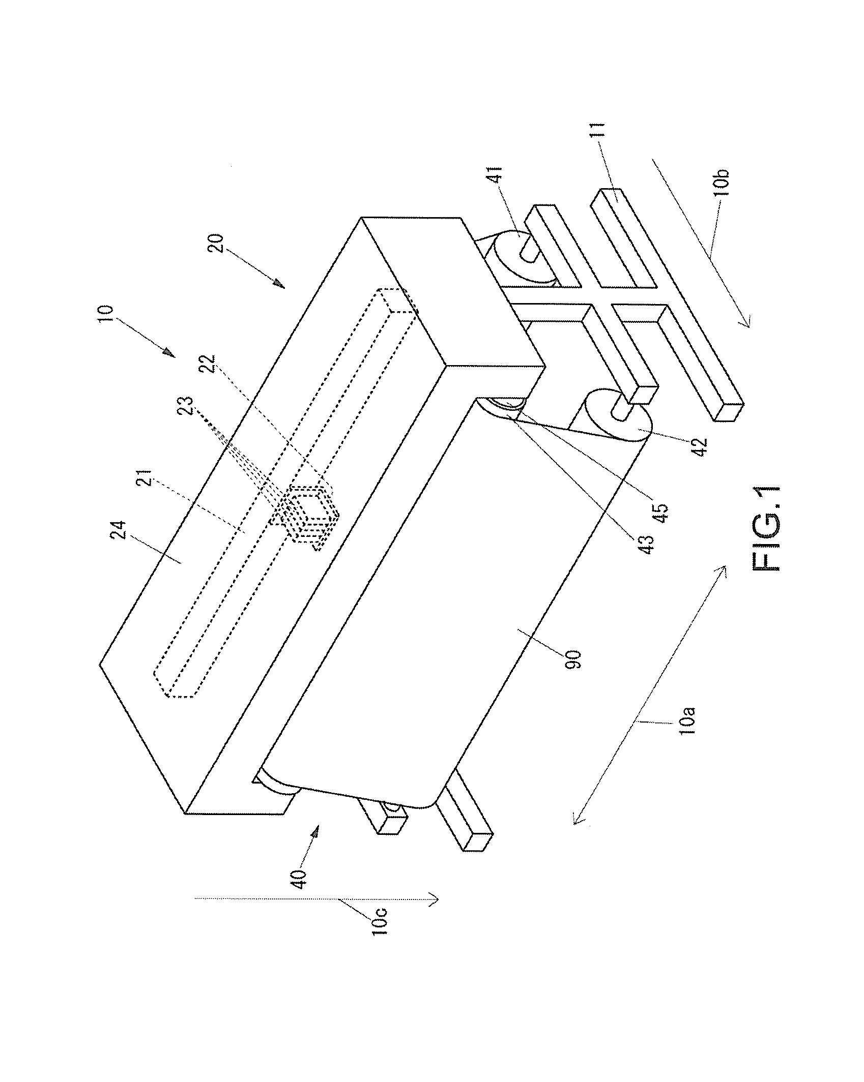
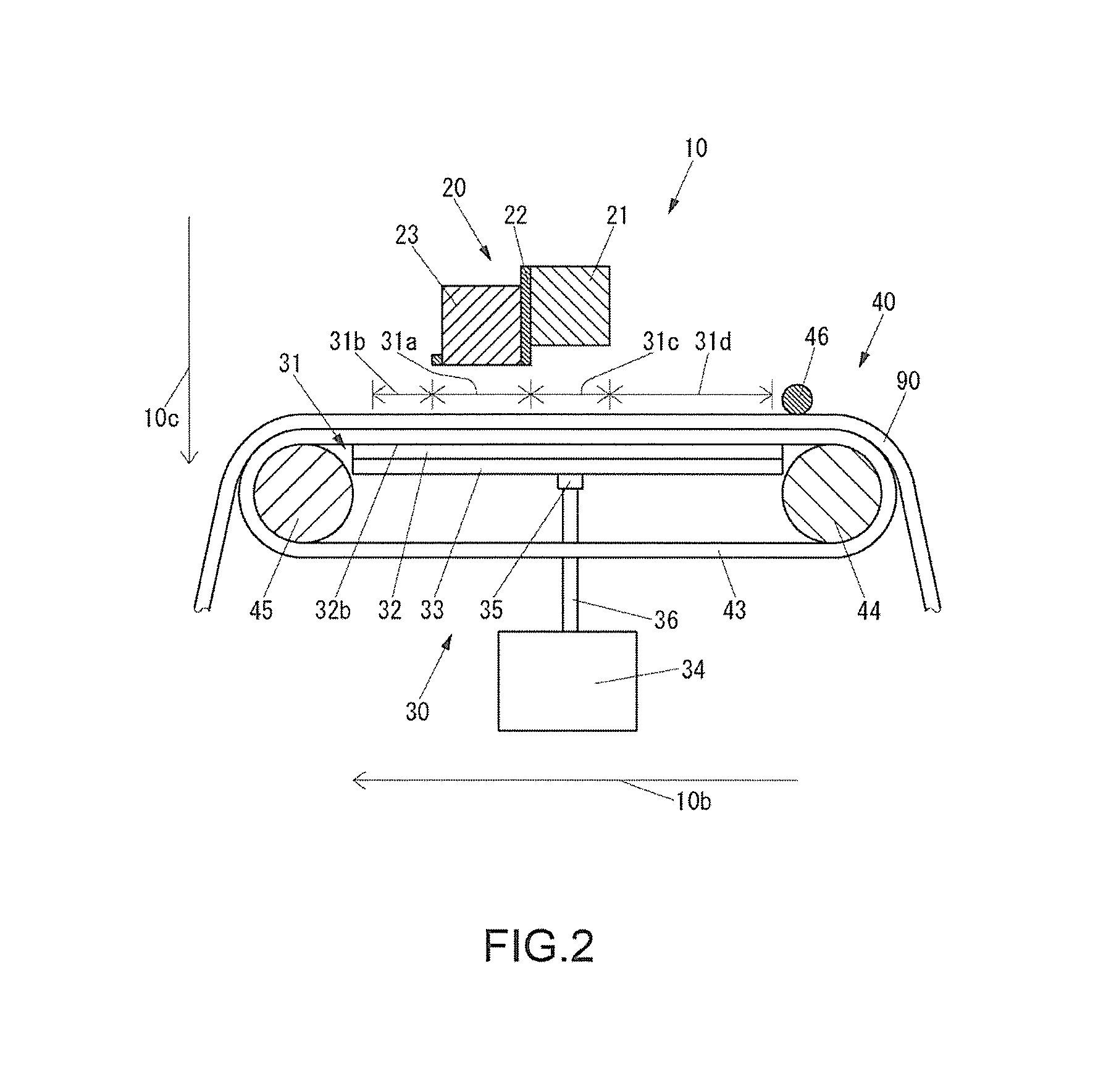
[0040]FIG. 1 is a perspective view illustrating the external appearance of an inkjet printer 10 according to the first embodiment. FIG. 2 is a cross-sectional view of a portion of the inkjet printer 10 as seen from the right side thereof. FIG. 3 is a cross-sectional view of a portion of the inkjet printer 10 as seen from the front side thereof.

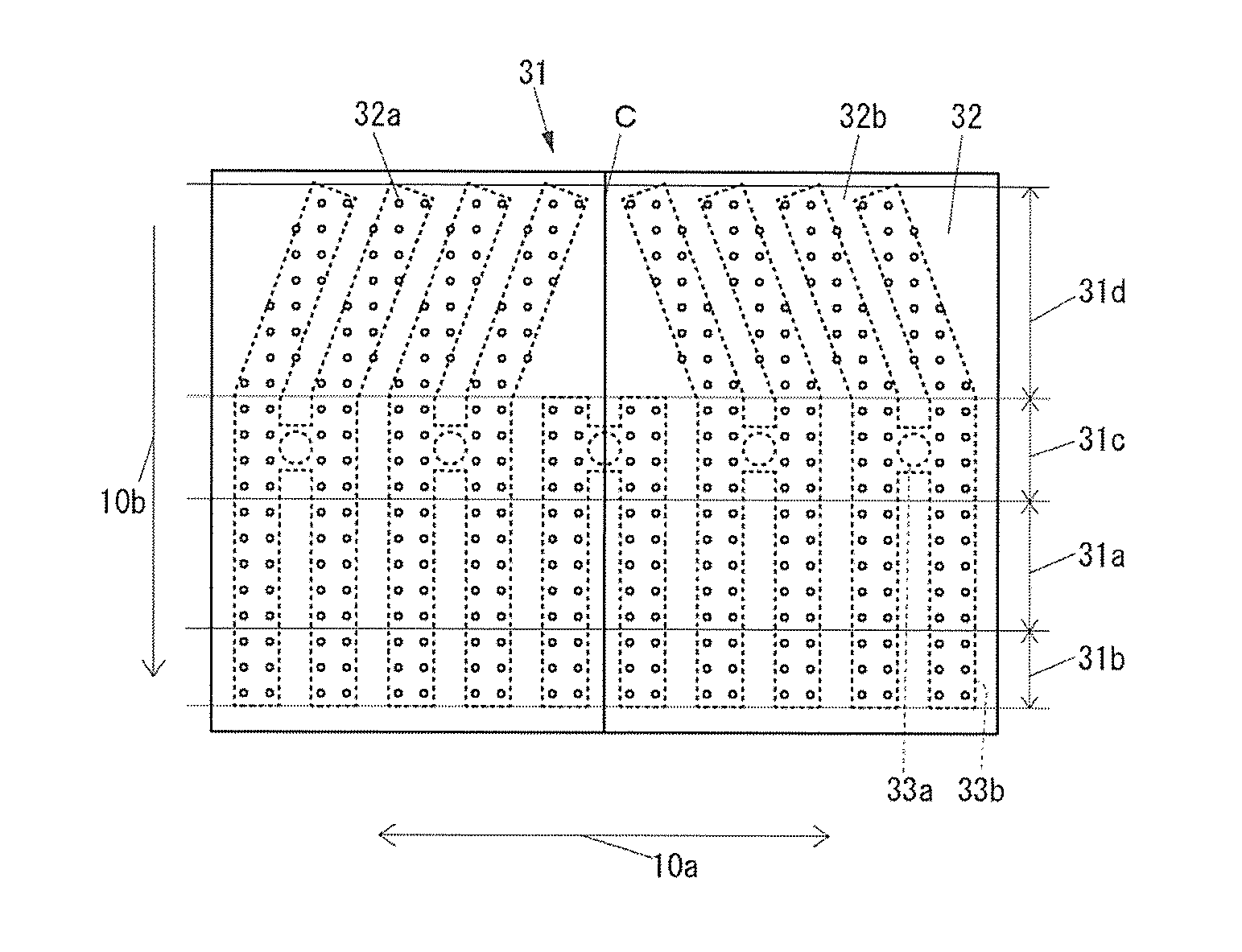
[0041]As shown in FIGS. 1 to 3, the inkjet printer 10 includes a leg part 11 which is installed on a floor, a main body 20 which is supported on the leg part 11 and extends in a direction shown by an arrow 10a, a medium adsorbing device 30 which includes a medium adsorbing unit 31 for adsorbing each medium 90, and a medium conveying device 40 which conveys each medium 90 adsorbed by the medium adsorbing device 30, with respect to the medium adsorbing unit 31, in a sub scan direction shown by an arrow 10b and perpendicular to the direction sh...

second embodiment

[0086]First, the configuration of an inkjet printer according to a second embodiment will be described.

[0087]In the configuration of the inkjet printer according to the second embodiment, components identical to the components of the inkjet printer 10 (see FIG. 1) according to the first embodiment are denoted by the same reference symbols, and will not be described.

[0088]The configuration of the inkjet printer according to the second embodiment is the same as a configuration which is obtained by replacing the medium adsorbing unit 31 (see FIG. 6) of the inkjet printer 10 with a medium adsorbing unit 131 shown in FIG. 13.

[0089]FIG. 13 is a plan view of the medium adsorbing unit 131 of the inkjet printer according to the second embodiment. FIG. 14 is a plan view of a base plate 133 of the medium adsorbing unit 131.

[0090]The configuration of the medium adsorbing unit 131 is the same as the configuration of the medium adsorbing unit 31 except for a configuration to be described below.

[0...


PUM


Abstract

An inkjet printer capable of suppressing a reduction in adsorption power relative to media as compared to the related art is provided. The inkjet printer includes a medium adsorbing device that has a medium adsorbing unit for adsorbing a medium, and an inkjet head that faces a portion of the medium adsorbing unit with a medium interposed therebetween. The medium adsorbing unit has a plurality of suction holes for sucking gas in order to adsorb a medium on an adsorption surface positioned on a side of the inkjet head. The medium adsorbing unit has a printing section and a downstream side adjacent section on a side of the adsorption surface. In the printing section, printing is performed on each medium by the inkjet head.

Description

CROSS REFERENCE TO RELATED APPLICATIONS[0001]This application claims the priority benefit of Japan Application No. 2015-045360, filed on Mar. 6, 2015. The entirety of the above-mentioned patent application is hereby incorporated by reference herein and made a part of this specification.TECHNICAL FIELD[0002]The disclosure relates to an inkjet printer which conveys a medium while adsorbing the medium for printing.DESCRIPTION OF THE BACKGROUND ART[0003]In the related art, there is known an inkjet printer which conveys a medium while adsorbing the medium for printing, and includes a medium adsorbing device including a medium adsorbing unit for adsorbing a medium, an inkjet head configured so as to face a portion of the medium adsorbing unit with a medium interposed therebetween and perform printing on the medium with ink, and a medium conveying device for conveying a medium adsorbed by the medium adsorbing device, with respect to the medium adsorbing unit (see Patent Document 1 for inst...

Claims


Application Information

Patent Timeline
Patent Type & Authority Patents(United States)
IPC IPC(8): B41J29/393B41J11/00B41J2/01
CPCB41J11/0085B41J2/01B41J11/007
Inventor ITO, SHINTAKANO, TOMOHIRO
Owner MIMAKI ENG
Why Eureka
Try Eureka