
Climbing vehicle with suspension mechanism

a technology of suspension mechanism and climbing vehicle, which is applied in the direction of endless track vehicles, vehicles, transportation and packaging, etc., can solve the problems of increasing kinematic requirements for steering, increasing complexity of system, and reducing efficiency

Active Publication Date: 2016-08-30
BEARD JAMES WALTER +2
View PDF11 Cites 6 Cited by
  • Summary
  • Abstract
  • Description
  • Claims
  • Application Information

AI Technical Summary

Benefits of technology

The invention is a new type of climbing vehicle that can carry a heavy load and has the ability to climb surfaces with varying geometries. It does this by using a suspension system called a resilient runner that efficiently distributes the climbing forces and maintains a constant distance between the vehicle and the surface. The invention can also self-reattach to the surface and offers a flexible suspension system that can accommodate variations in the surface geometry. Overall, the invention provides a unique solution for high-load, flexible, and efficient climbing.

Problems solved by technology

The primary difficulty in using a wheeled-type platform for climbing is that the wheels require theoretical point contact with the surface to enable efficient rolling.
While the overall adhering force of the vehicle can be increased by increasing the number of wheels in contact with the climbing surface, this raises several technical difficulties in the design and implementation of these systems.
First, as the number of wheels increases, the complexity of the system increases.
Third, as the number of wheels in contact with the surface increases, the kinematic requirements for steering increase, or slipping is introduced into the system which decreases efficiency.
This concentration of forces on a single wheel results in a reduced payload capacity of the climbing vehicle.
Thus, wheel-type climbing robot vehicles that place the adhering members in our about the wheels have limitations in the payload capacity.
The design that places the adhering member directly in the chassis encounters significant performance limitations however when the system is used on a surface that is not flat, or has protrusions or indentions in the surface.
This limitation arises from a technical difficulty that the chassis cannot conform to variations in the geometry of the climbing surface, such that the distance between the chassis and surface is changing during operation.
The decreased adhering force limits the available payload, thus limiting the performance of this type of invention.
Thus, small displacements between the chassis and the climbing surface, caused by variations in the surface geometry, are greatly magnified and reduce the actual attraction force.
For tracked systems with the adhering members or magnets located in the tracks, the difficulty becomes in simultaneously allowing the tracks to conform to the climbing surface while transferring forces between all elements along the track and the vehicle body.
The majority of patents employing endless tracks with adhering members in the tracks do not provide a means to distribute climbing forces among the track elements.There are a few special cases of note that do provide a means to distribute the climbing forces among more than 3 of the discrete magnets.
A primary limitation of the U.S. Pat. No. 7,624,827 invention is that it does not permit a mechanism to return a distributed magnet back to the wall if the pulling force exceeds the magnet force.
The primary limitation of US application publication number US 2012 / 0111649 A1 is that the tracks with exterior magnets create a non-constant pitch distance and therefor non-uniform velocity transmission between input and output.
While the number of wheels is not specified or unique in the claims, and therefore not limiting to a large number of magnetic wheels, these patents do not address the kinematic constraints that are imposed when additional wheels are added in order to maintain wheel roll without slip.
Additionally, these patents do not address potential slip conditions.

Method used


Image

  • Climbing vehicle with suspension mechanism
  • Climbing vehicle with suspension mechanism
  • Climbing vehicle with suspension mechanism

Examples


Embodiment Construction

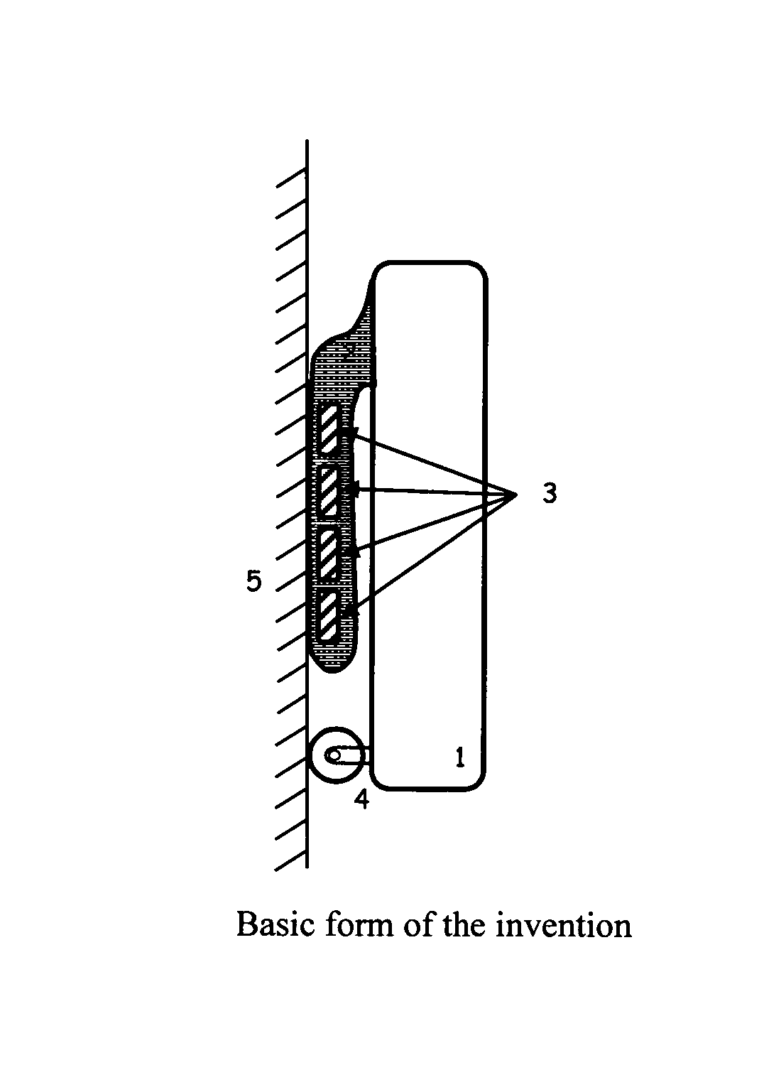
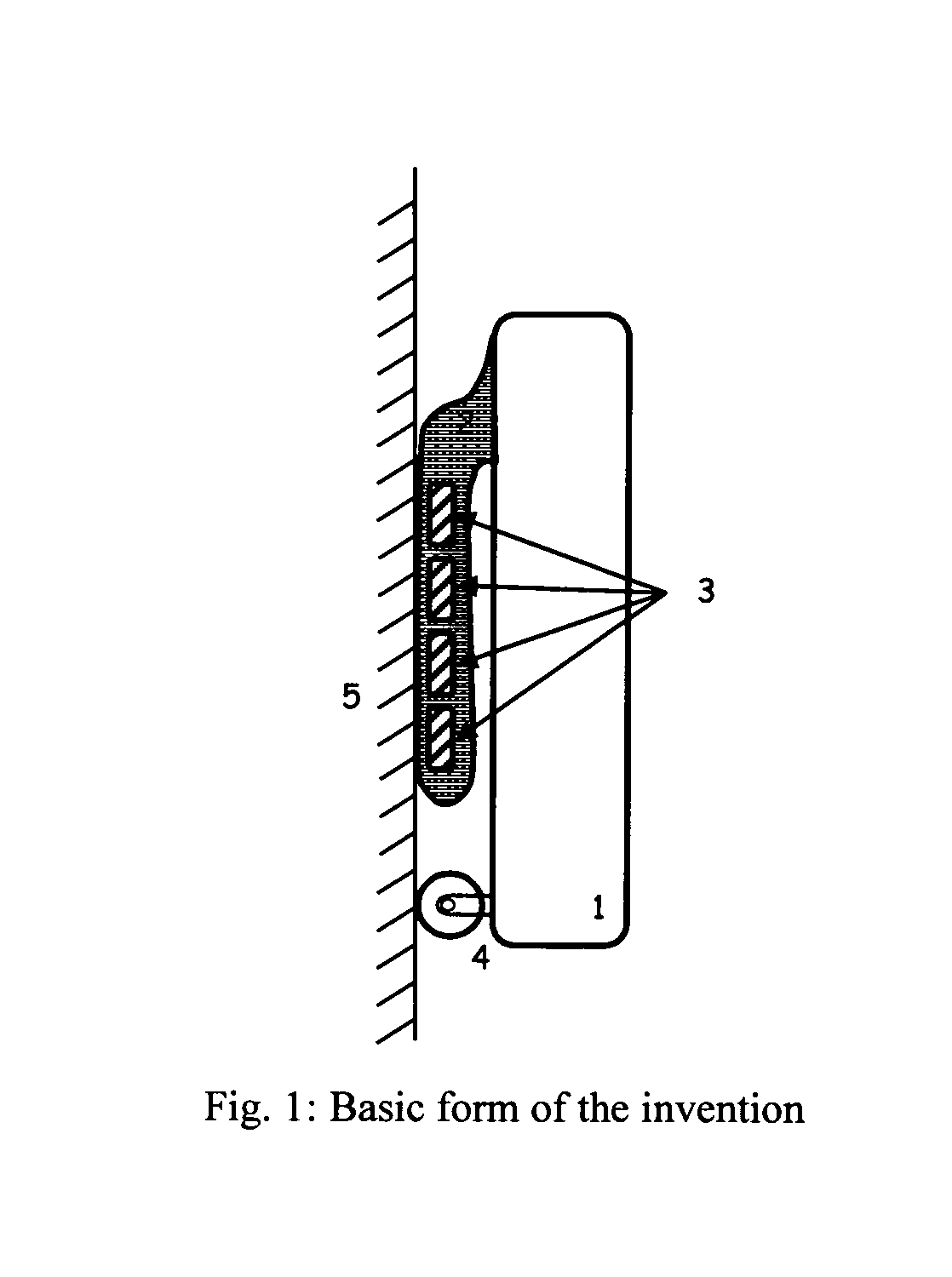
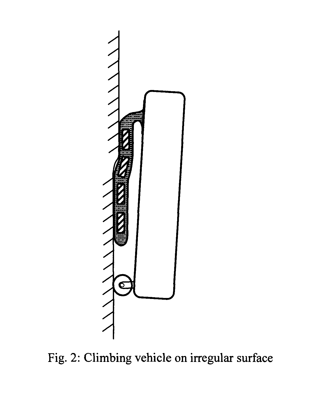
[0045]The invention disclosed here describes a climbing vehicle, robot or platform that is able to climb ferrous surfaces while accommodating variations in the geometry of the climbing surface and effectively transferring forces between the adhering members and the vehicle chassis. In a basic form, the invention consists of a chassis (1), resilient runner (2), adhering members (3) and a propulsion element (4) as shown in FIG. 1. The climbing vehicle is operating on a climbing surface (5) that may contain variations in geometry. The chassis forms the body of the vehicle and can be used to mount payloads, tools or other components. The resilient runner is attached to the chassis and makes sliding contact with the climbing surface. The resilient runner can deform to generally adapt or conform to the climbing surface (FIG. 2). The adhering members are attached to the resilient runner, for example through a bolted connection, a glued connection, fit into a molded shape in the resilient r...


PUM


Abstract

A climbing vehicle capable of high payload to weight ratio and capable of climbing surfaces with geometric variations is enabled through a suspension mechanism consisting of a resilient runner chain. The resilient runners contain adhering members such as magnets that create forces directed toward a ferrous climbing surface. The resilient runner has flexibility and internal stiffness or additional springs that transfer these forces to the climbing vehicle chassis and payload to provide equilibrium during the climbing process. It is able to conform to a large range of surface irregularities while providing push and pulling forces between the adhering members and the climbing vehicle chassis to uniformly distribute the climbing loads on the adhering members. The result is a climbing machine that can accommodate large surface irregularities while maximizing the climbing payload with a minimum number and size of adhering members.

Description

STATEMENT REGARDING FEDERALLY SPONSORED RESEARCH OR DEVELOPMENT[0001]Not ApplicableDESCRIPTION OF ATTACHED APPENDIX[0002]Not ApplicableBACKGROUND OF THE INVENTION[0003]This invention applies to a category of self-propelled, climbing vehicles that primarily make use of wheels or endless tracks to provide propulsion along a climbing surface, but could employ legs. For this purpose, the term climbing vehicle refers to a vehicle that is capable of traversing a surface horizontally or vertically in some inclined or inverted position relative to the earth horizon. Further, it is intended that the climbing vehicle is able to accommodate irregularity in the climbing surface including convex or concave regions. Such climbing vehicles may be used to conduct remote operations such as inspection, maintenance, or manufacturing in environments that pose difficulty or danger for human operation. These climbing vehicles could also be used in a wide variety of applications including power production...

Claims


Application Information

Patent Timeline
Patent Type & Authority Patents(United States)
IPC IPC(8): B62D55/00B62D55/265B62D55/075B62D55/104B62D55/02
CPCB62D55/02B62D55/075B62D55/104B62D55/265
Inventor BEARD, JAMES WALTERCANFIELD, STEPHEN LEEBRYANT, DAVID ANDREW
Owner BEARD JAMES WALTER
Learn More