Spool shuttle crossover valve in split-cycle engine

a technology of cross-over valve and split-cycle engine, which is applied in the direction of oscillatory slide valve, machine/engine, mechanical equipment, etc., can solve the problems of reducing the effective compression ratio of the engine below that of a conventional engine, and failing to disclose the effective regulation of the transfer of working fluid, so as to reduce the leakage of thermal energy

Active Publication Date: 2016-09-06
TOUR ENGINE INC
View PDF21 Cites 3 Cited by
  • Summary
  • Abstract
  • Description
  • Claims
  • Application Information

AI Technical Summary

Benefits of technology

[0038]In some exemplary embodiments, the internal chamber, a compression chamber, and an expansion chamber are sized to minimize dead space.
[0045]In some exemplary embodiments, the second cylinder includes a plurality of exhaust heating passages for utilizing heat provided by exhaust gases expelled by the second piston to further heat the second cylinder and is thermally isolated from the surrounding environment so as to reduce leakage of thermal energy from the second cylinder.
[0064]In some exemplary embodiments of the method, the internal chamber, a compression chamber, and an expansion chamber are sized to minimize dead space.
[0070]In some exemplary embodiments of the method, the second cylinder includes a plurality of exhaust heating passages for utilizing heat provided by exhaust gases expelled by a second piston to further heat the second cylinder and is thermally isolated from the surrounding environment so as to reduce leakage of thermal energy from the second cylinder.

Problems solved by technology

The references described above, however, fail to disclose how to effectively govern the transfer of the working fluid in a timely manner and without pressure loss from the compression cylinder to the power cylinder, using a valve system that is durable with high level of sealing.
In addition, the separate cylinders disclosed in these references are all connected by a transfer valve or intermediate passageway (connecting tube) of some sort that yields a substantial volume of “dead space” between cylinders reducing the effective compression ratio of the engine below that of a conventional engine.

Method used


Image

  • Spool shuttle crossover valve in split-cycle engine
  • Spool shuttle crossover valve in split-cycle engine
  • Spool shuttle crossover valve in split-cycle engine

Examples


Embodiment Construction

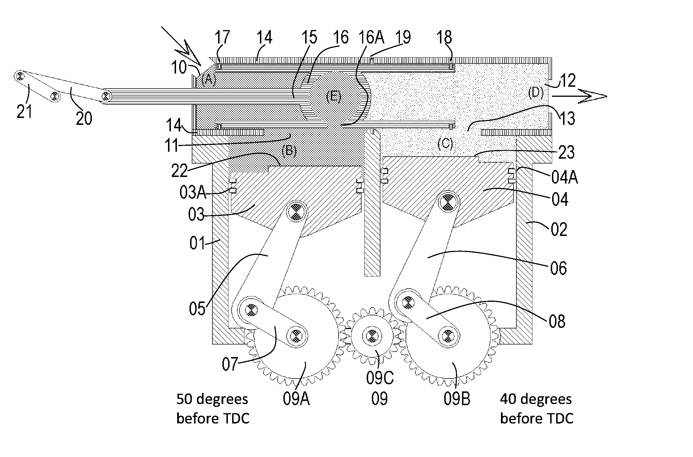
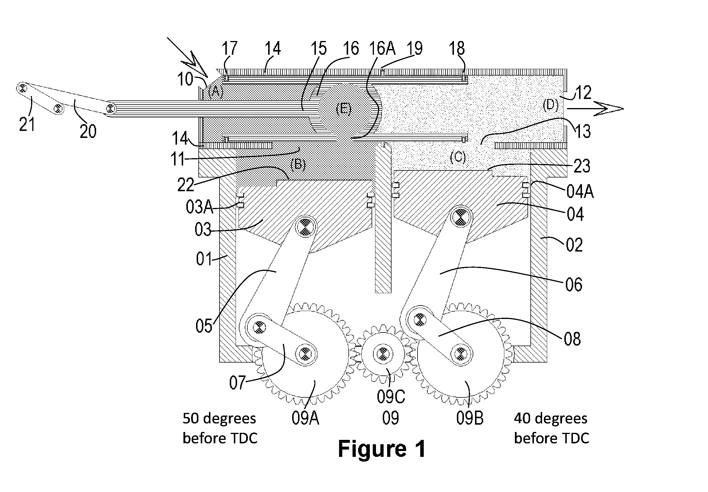
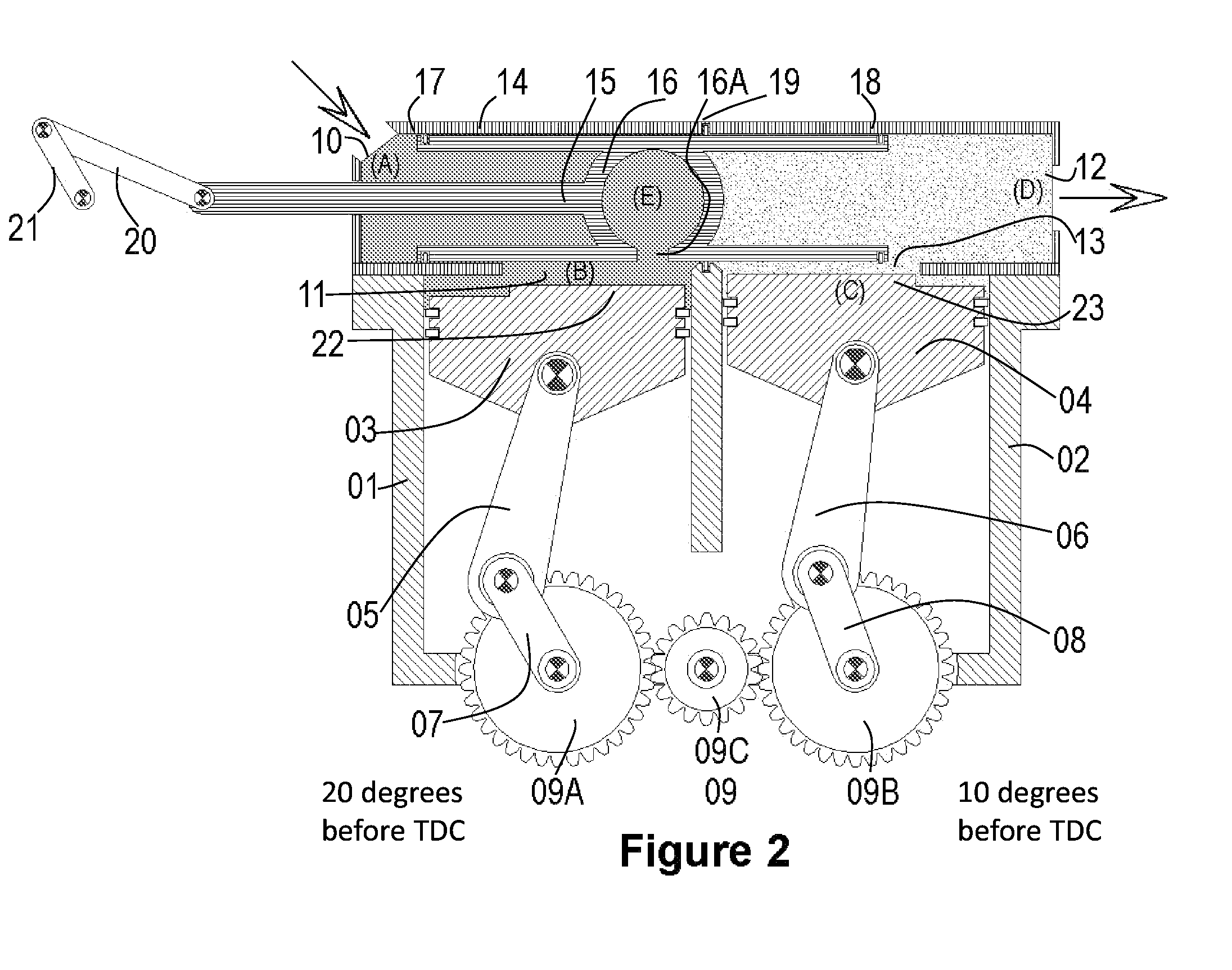
[0108]The embodiments are described in detail below with reference to the figures, wherein similar elements are referenced with similar numerals throughout. It is understood that the figures are not necessarily drawn to scale. Nor do they necessarily show all the details of the various exemplary embodiments illustrated. Rather, they merely show certain features and elements to provide an enabling description of the exemplary embodiments.

[0109]In some exemplary embodiments described herein, a split-cycle engine includes a valve chamber with a valve residing therein. The valve may include an internal chamber that selectively fluidly couples a cold and a hot cylinder of the engine. The valve and internal chamber may move within the valve chamber and relative to the hot and cold cylinders.

[0110]In some exemplary embodiments, the valve may experience reduced inertia forces. This may allow for increased durability and reliability. In some exemplary embodiments, the engine may experience t...


PUM


Abstract

A split-cycle engine includes: a first cylinder housing a first piston, wherein the first piston performs an intake stroke and a compression stroke, but does not perform an exhaust stroke; a second cylinder housing a second piston, wherein the second piston performs an expansion stroke and an exhaust stroke, but does not perform an intake stroke; and a valve chamber housing a valve, the valve comprising an internal chamber that selectively fluidly couples to the first and second cylinders, wherein the valve and internal chamber move within the valve chamber and relative to the first and second cylinders.

Description

CROSS-REFERENCE TO RELATED APPLICATIONS[0001]This application is a U.S. National Stage of International Application No. PCT / US2014 / 047076, filed Jul. 17, 2014 which claims the benefit of U.S. Provisional Application No. 61 / 847,551, filed Jul. 17, 2013, the contents of which are incorporated herein by reference in their entireties.BACKGROUND OF THE INVENTION[0002]1. Field of the Invention[0003]This disclosure relates generally to split-cycle internal combustion engines also known as split-cycle engines and, more specifically, to crossover valves.[0004]2. Description of the Related Art[0005]Conventional internal combustion engines include one or more cylinders. Each cylinder includes a single piston that performs four strokes, commonly referred to as the intake, compression, combustion / power / expansion, and exhaust strokes. Together, these four strokes form a complete cycle of a conventional internal combustion engine. However, each part of the cycle is affected differently by the heat...

Claims


Application Information

Patent Timeline
Patent Type & Authority Patents(United States)
IPC IPC(8): F02B33/22F01L7/02F01L1/46F01L7/16F01L1/053F02B41/06
CPCF01L7/02F01L1/46F01L7/16F02B33/22F01L2001/0535F01L2101/00F01L2101/02F02B41/06F01L2301/02F01L2301/00Y02T10/12F01P1/02F01P3/02F01P7/16F01P2001/023F01P2003/022F02B5/02F02B9/04F02P13/00
Inventor TOUR, BENJAMIN HUGOTOUR, ODEDTOUR, GILADSIVAN, EHUDWAHL, MICHAEL H.
Owner TOUR ENGINE INC
Why Eureka
Try Eureka