Drive unit

a technology of drive unit and worm gear, which is applied in the direction of belt/chain/gearing, toothed gearing, belt/chain/gearing, etc., can solve the problems of poor meshing between the worm shaft and the worm gear, the diameter of the motor shaft is reduced, and the strength of the motor shaft is decreased

Active Publication Date: 2016-09-06
JOHNSON ELECTRIC SA
View PDF18 Cites 10 Cited by
  • Summary
  • Abstract
  • Description
  • Claims
  • Application Information

AI Technical Summary

Benefits of technology

[0012]Preferably, radial outward protrusions are formed on the motor shaft, and the protrusions press against an inner surface of the worm shaft, forming elastic deformation of the inner surface to prevent relative rotational displacement between the worm shaft and the motor shaft.
[0015]Preferably, the protrusions are arranged at a position corresponding to a middle portion of the worm shaft to prevent relative axial displacement between the worm shaft and the motor shaft.
[0020]A drive unit according to the present invention uses a sleeve that is press fitted onto the motor shaft to transmit the torque of the motor shaft to the worm shaft, to overcome the problem of how to reliably connect the plastic worm shaft to the motor shaft, without compromising the strength of the motor shaft.

Problems solved by technology

However, this reduces the diameter of the motor shaft resulting in a decrease in the strength of the motor shaft.
The motor shaft is vulnerable to bending due to the relatively large output torque of the motor, resulting in poor meshing between the worm shaft and the worm gear, even malfunction of the drive unit.

Method used


Image

  • Drive unit
  • Drive unit
  • Drive unit

Examples


Embodiment Construction

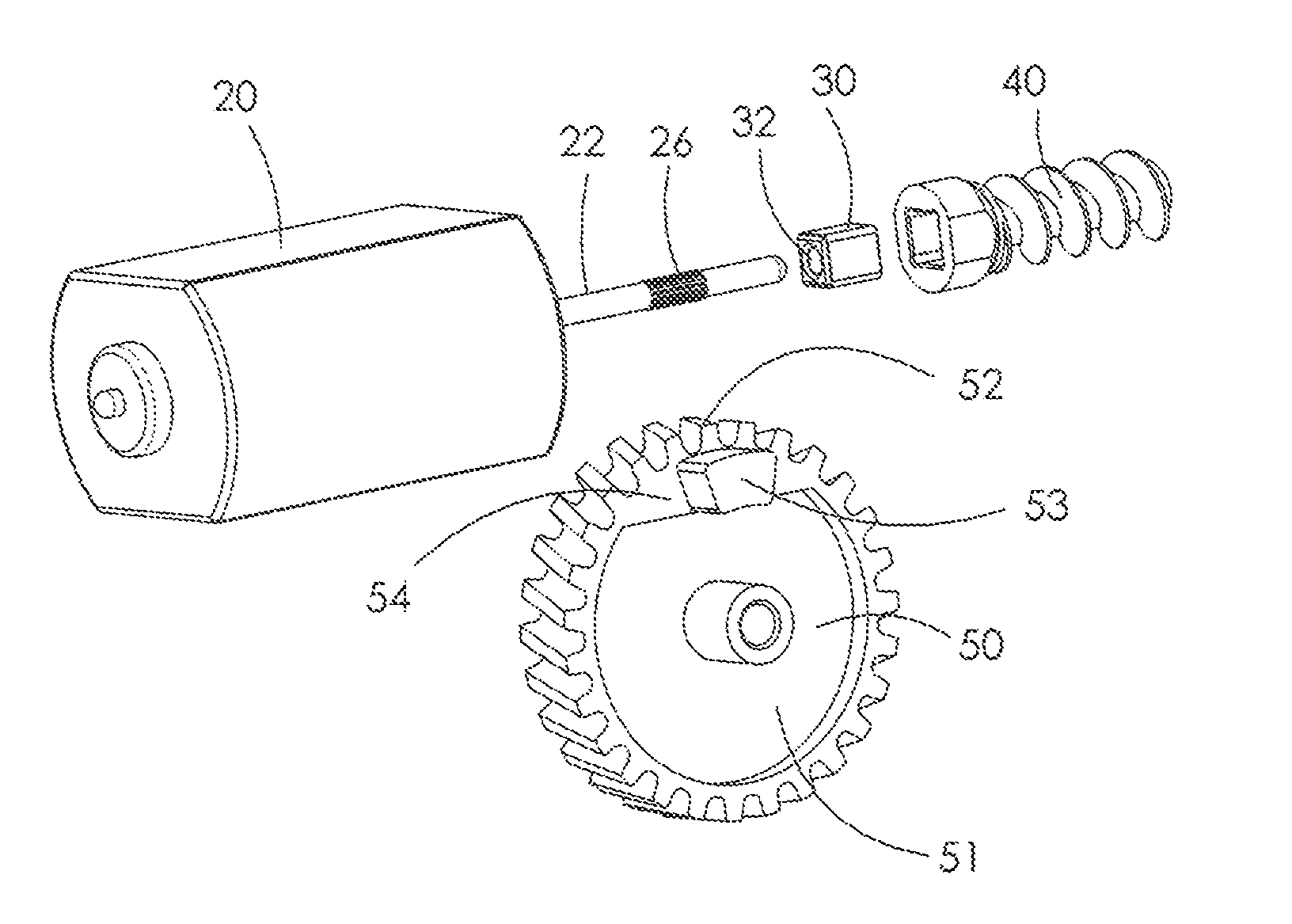
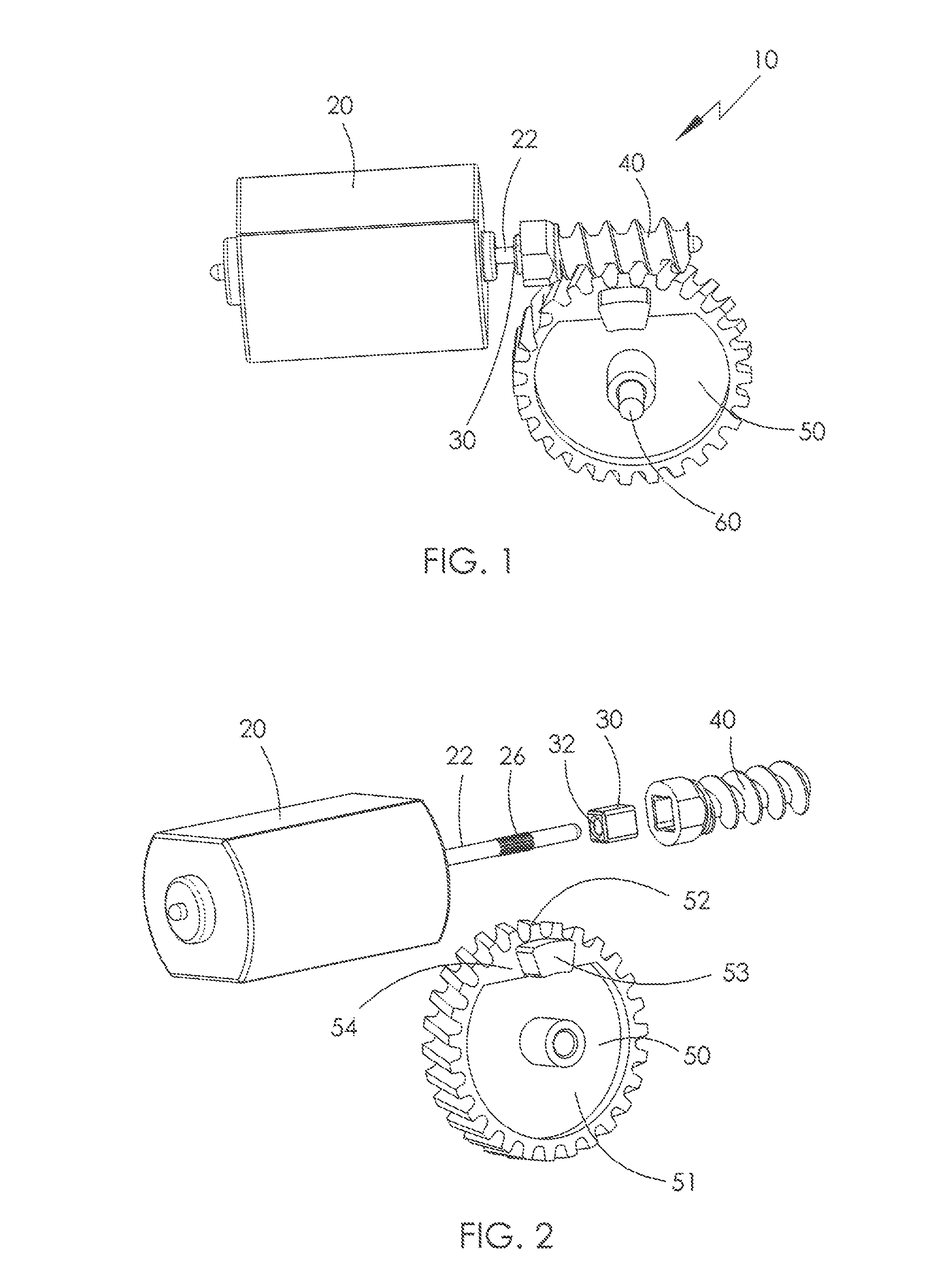
[0029]Referring to FIG. 1 and FIG. 2, a drive unit 10, according to an exemplary embodiment of the present invention, comprises a motor 20 having a motor shaft 22, a sleeve 30 tightly sleeved on the motor shaft 22, a worm shaft 40 fitted to the motor shaft 22 and the sleeve 30, a worm gear 50 engaged with the worm shaft 40, and an output shaft 60 coupled to the worm gear 50. The output shaft 60 couples to a driven member (not shown). During operation of the drive unit 10, the motor 20 rotates the worm shaft 40 by way of the sleeve 30, and the worm shaft 40 rotates the worm gear 50. In this manner, the torque of motor 20 is transmitted to the driven member.

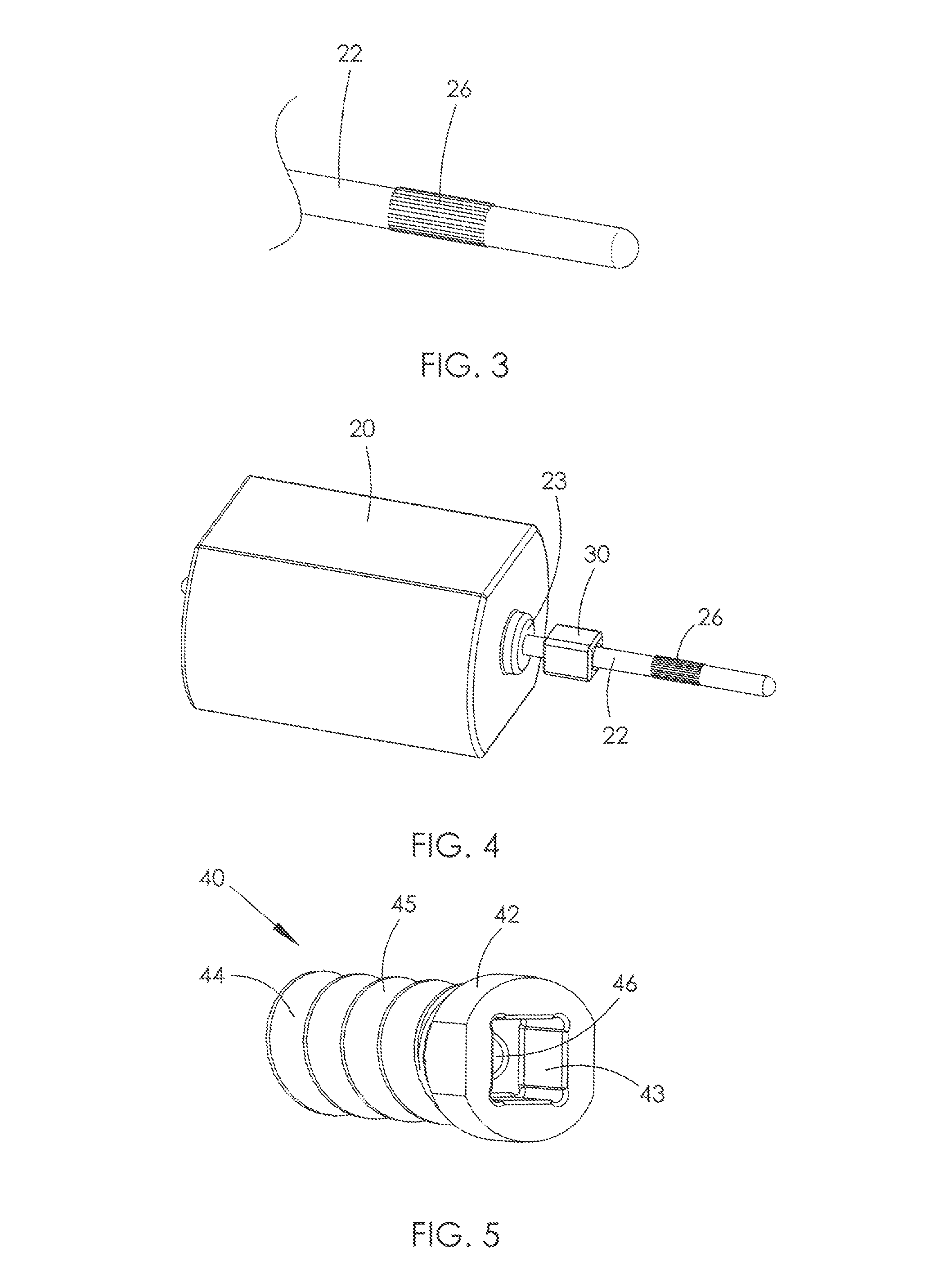
[0030]FIG. 3 is an enlarged detail view of a portion of the distal end of the motor shaft 22. As shown, the motor shaft is right cylindrical, i.e. the motor shaft has a circular cross section. Preferably, a number of protrusions 26 are formed on the motor shaft 22. Each of the protrusion protrudes radially and outwardly. More speci...


PUM


Abstract

A drive unit includes an electric motor, a worm shaft coupled to the motor, a worm gear engaging with the worm shaft, and an output shaft connected to the worm gear. The motor has a motor shaft on which the worm shaft is fixed. The worm shaft is made of plastic. The drive unit further includes a metallic sleeve press fitted to the motor shaft. An outer profile of the sleeve is non-circular. A correspondingly shaped receiving hole is formed in the worm shaft to receive the sleeve. The sleeve rotates with the motor shaft and drives the worm shaft.

Description

CROSS REFERENCE TO RELATED APPLICATIONS[0001]This non-provisional patent application claims priority under 35 U.S.C. §119(a) from Patent Application No. 201210037101.7 filed in The People's Republic of China on Feb. 17, 2012.FIELD OF THE INVENTION[0002]This invention generally relates to a drive unit, and particularly to a drive unit comprising an electric motor driving an output via a worm and worm gear.BACKGROUND OF THE INVENTION[0003]Such a drive unit usually comprises a motor, a worm shaft and a worm gear. The worm shaft connects the shaft of the motor to the worm gear, and transmits output of the motor to the worm gear. Traditional drive units use a metal worm shaft pressed onto the motor shaft and a metal worm gear. To lower the cost, plastic worms and worm gears have replaced the metal worms and worm gears. However, how to effectively and efficiently transmit the motor torque to a plastic worm shaft is a subject to be resolved. One solution is to make the motor shaft with a D...

Claims


Application Information

Patent Timeline
Patent Type & Authority Patents(United States)
IPC IPC(8): F16H1/16F16H57/00
CPCF16H1/16F16H57/0025Y10T74/19828
Inventor CHEUNG, CHI WANGWU, ZHONG PINGDING, HONG YU
Owner JOHNSON ELECTRIC SA
Why Eureka
Try Eureka