Connector with a locking and unlocking mechanism

a technology of locking and unlocking mechanism and connector, which is applied in the direction of connection, electrical apparatus, coupling device connection, etc., can solve the problems of increasing the intensive degree of the receptacle connector in electronic equipment, increasing the complexity of the mechanism attaching or detaching the qsfp connector from the shielding case, and achieving efficient locking and efficient unlocking

Active Publication Date: 2016-09-06
BIZLINK ELECTRONICS KUNSHAN CO LTD
View PDF11 Cites 2 Cited by
  • Summary
  • Abstract
  • Description
  • Claims
  • Application Information

AI Technical Summary

Benefits of technology

[0007]An object of the present invention is to provide a connector with a locking and unlocking mechanism, which can be locked and unlocked and the locking and unlocking operation of which is extremely convenient and fast.
[0019]In comparison with the prior art, the connector with a lock and unlock mechanism of the present invention can be efficiently locked in a shielding case by disposing the vertical stop wall on the case, can be efficiently unlocked by the bending end of the unlocking member, and can be restored to the initial state under the function of the spring member. It can be seen that the locking and unlocking way of the connector is very convenient and fast.

Problems solved by technology

However, the connector is becoming smaller and smaller, and the intensive degree of the receptacle connector in an electronic equipment is gradually increased.
Therefore, the mechanism attaching or detaching the QSFP connector from the shielding case becomes more complex, and the operation thereof also becomes more difficult.

Method used


Image

  • Connector with a locking and unlocking mechanism
  • Connector with a locking and unlocking mechanism
  • Connector with a locking and unlocking mechanism

Examples


Embodiment Construction

[0025]The following description of every embodiment with reference to the accompanying drawings is used to exemplify a specific embodiment, which may be carried out in the present invention. Directional terms mentioned in the present invention, such as “top”, “bottom”, “front”, “back”, “left”, “right”, “top”, “bottom” etc., are only used with reference to the orientation of the accompanying drawings. For example, the following description may refer to the orientation of FIG. 1. Therefore, the used directional terms are intended to illustrate, but not to limit, the present invention.

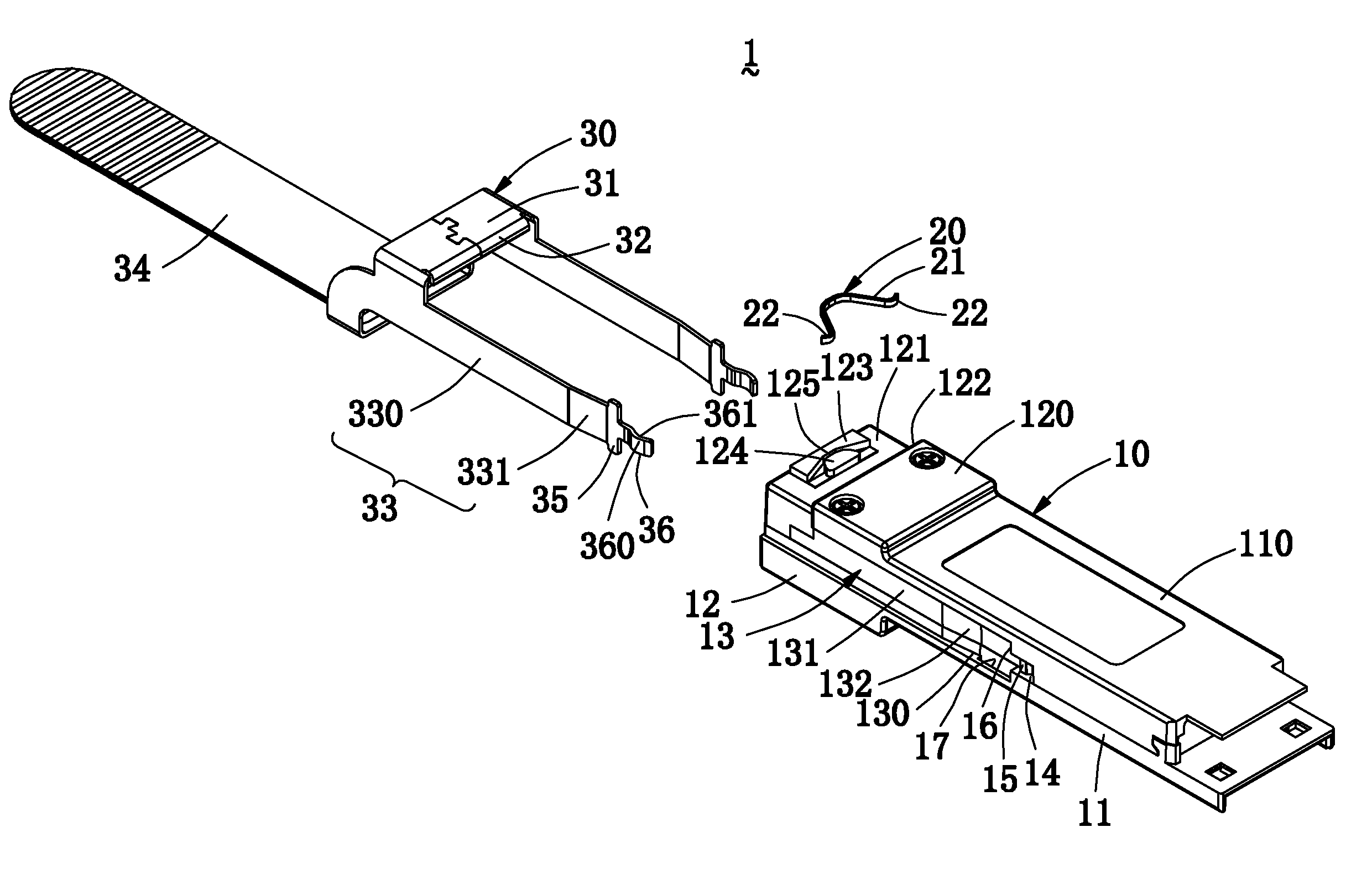
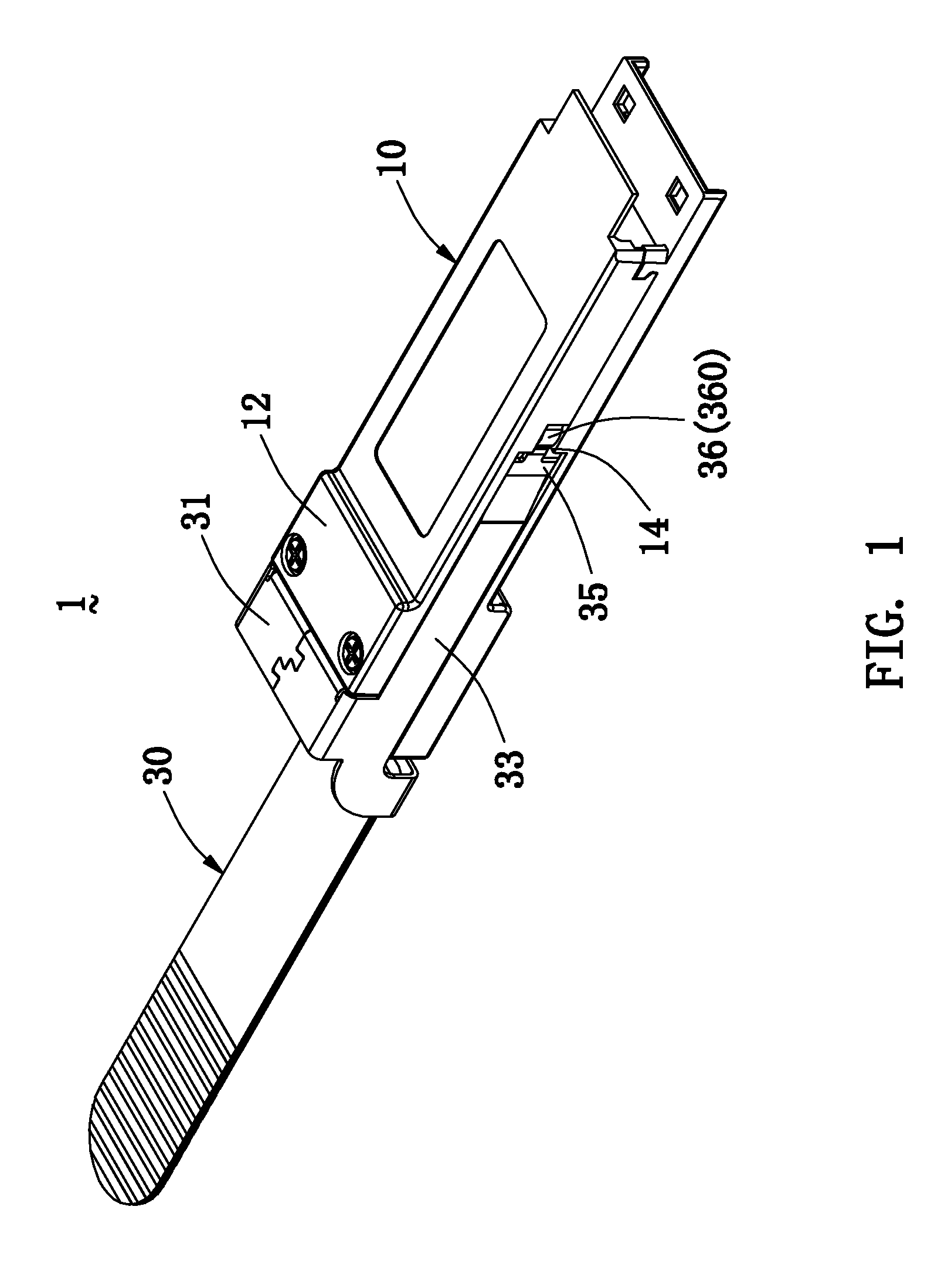
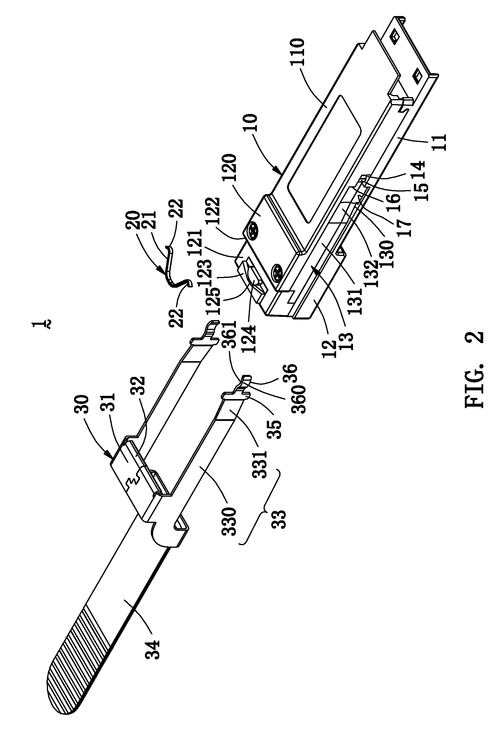
[0026]Please refer to FIGS. 1 to 4, a connector 1 with a locking and unlocking mechanism mainly comprises a case 10, a spring member 20 mounted on the case 10, and an unlocking member 30 mounted on the case 10.

[0027]Referring to FIG. 2, the case 10 has an inserting portion 11 located in the front thereof and a retaining portion 12 located in the rear thereof. A top surface 120 of the retaining portion 12 ...


PUM


Abstract

A connector with a locking and unlocking mechanism is disclosed. The connector includes a case, a spring member and an unlocking member. The case includes a guiding groove, a narrow groove, a protrusion, a vertical stop wall and a latching groove. The spring member and the unlocking member are mounted the case. The unlocking member includes a guiding arm, a latching plate and a bending end. A vertical portion of the unlocking member is inserted between the spring member and the case. The guiding arm extends into the corresponding guiding groove. The latching plate enters into the latching groove. The bending end enters into the narrow groove and covers the protrusion. When a pulling portion is pulled back, the vertical portion compresses the spring member, the latching plate slides back along the latching groove, and the bending end moves back along the protrusion.

Description

BACKGROUND OF THE INVENTION[0001]1. Field of the Invention[0002]The present invention relates to a connector technology and more particularly to a connector with a locking and unlocking mechanism.[0003]2. Description of the Prior Art[0004]A QSFP (Quad Small Form-factor Pluggable) connector is a high density and high speed pluggable connector. Generally, the QSFP connector disposes a locking mechanism. When the QSFP connector is connected to a receptacle connector, the QSFP connector is firstly inserted into a shielding case and is fixed in the shielding case by the locking mechanism, thereby ensuring the connection safety between the QSFP connector and the receptacle connector. When needing to disconnect the QSFP connector from the receptacle connector, the QSFP connector is firstly detached from the shielding case by an unlocking mechanism, so the QSFP connector can be fast pulled out from the receptacle connector.[0005]However, the connector is becoming smaller and smaller, and th...

Claims


Application Information

Patent Timeline
Patent Type & Authority Patents(United States)
IPC IPC(8): H01R13/627H01R13/631H01R13/633
CPCH01R13/6275H01R13/631H01R13/6335
Inventor YANG, HSIN CHIHYU, LEMENG, JIN HUA
Owner BIZLINK ELECTRONICS KUNSHAN CO LTD
Why Eureka
Try Eureka