Image-processing apparatus and image-processing method for generating a virtual angle of view
a technology of image processing apparatus and virtual angle of view, which is applied in the field of image processing apparatus and image processing method, can solve the problems of pixel enlargement magnification increase, large change in perceived resolution, and gradual so as to achieve smooth change of perceived resolution and not deterioration of perceived resolution
- Summary
- Abstract
- Description
- Claims
- Application Information
AI Technical Summary
Benefits of technology
Problems solved by technology
Method used
Image
Examples
embodiment 1
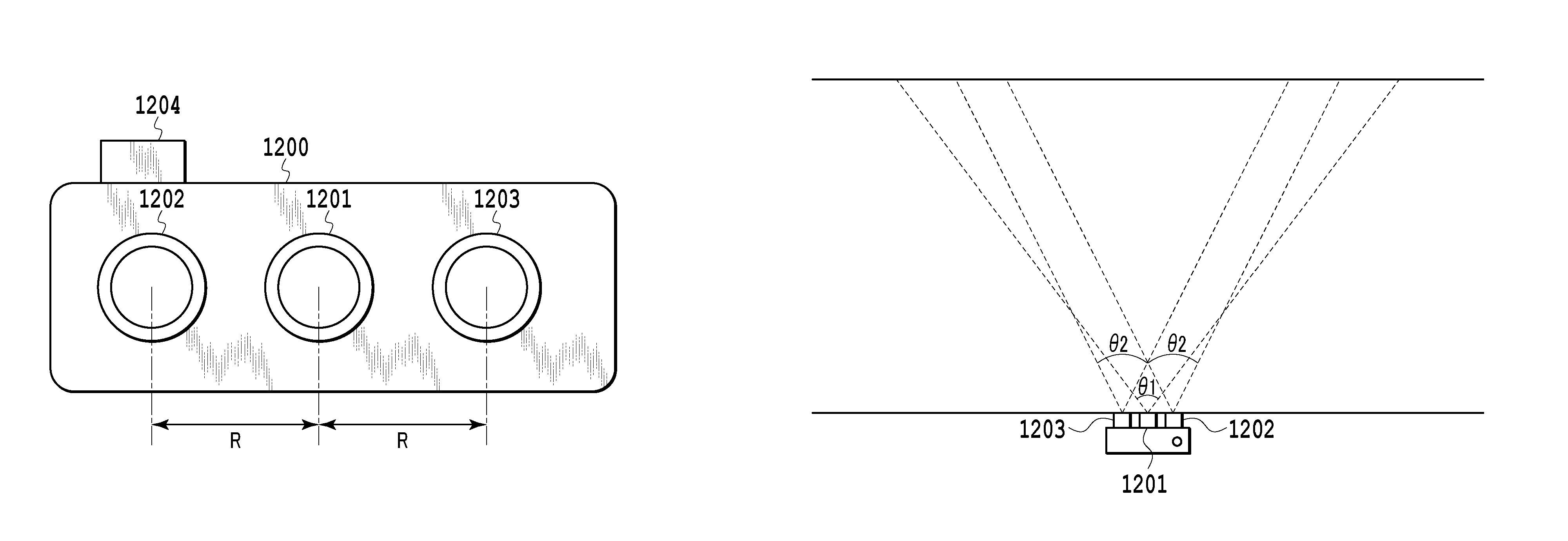
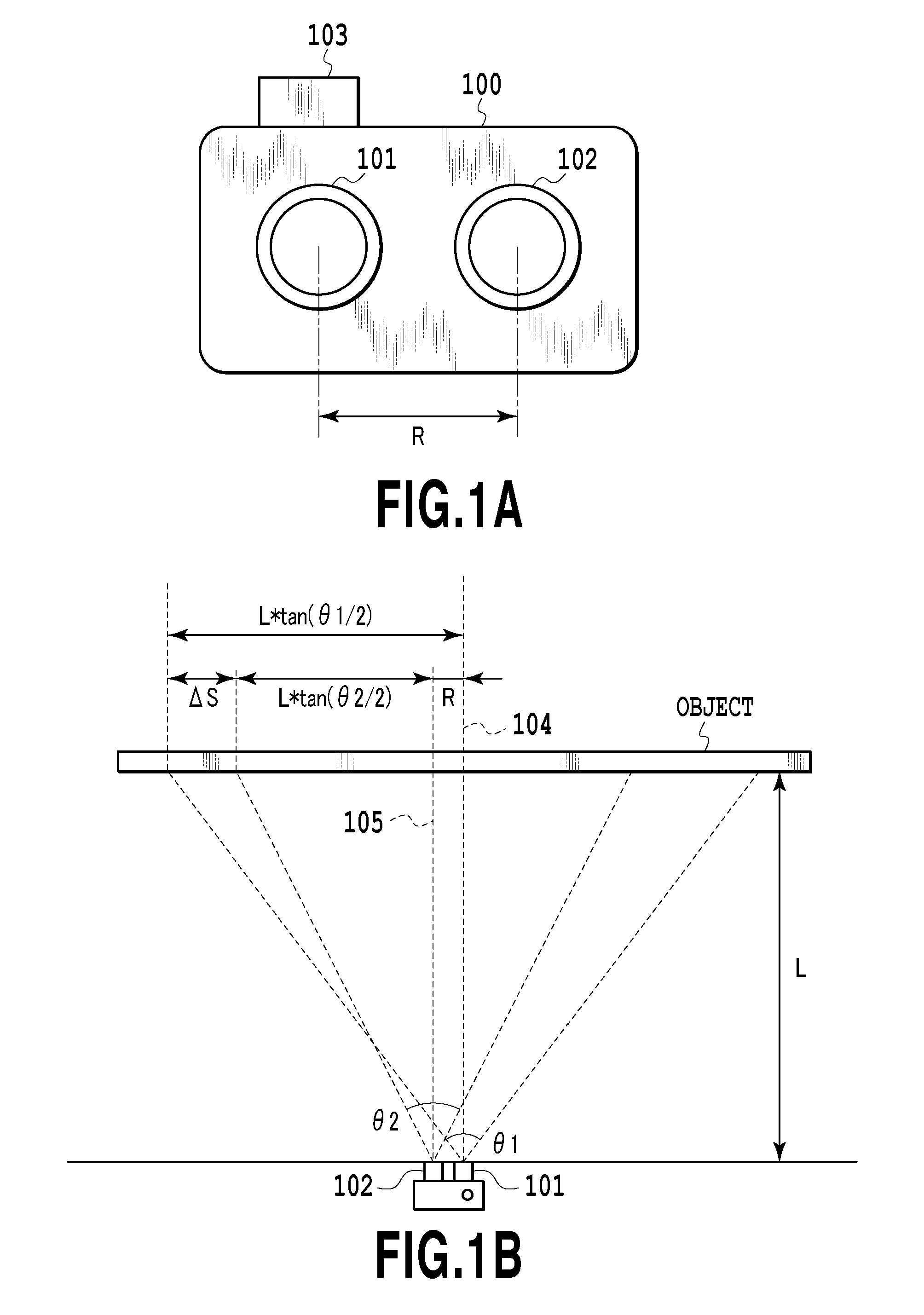
[0030]In this embodiment, virtual-angle-of-view image data corresponding to a virtual angle of view selected by the user is generated based on two pieces of captured image data of different angles of view and on the virtual angle of view. In this process, virtual-angle-of-view image data of a small zoom magnification can be obtained by setting the virtual angle of view to a large value, and virtual-angle-of-view image data of a large zoom magnification can be obtained by setting the virtual angle of view to a small value. In other words, by changing the virtual angle of view, the user can change the zoom magnification of the virtual-angle-of-view image data. This embodiment can be utilized as a process for generating preview image data at the time of image capture or as a process for generating image data zoomed with a given magnification after image capture.
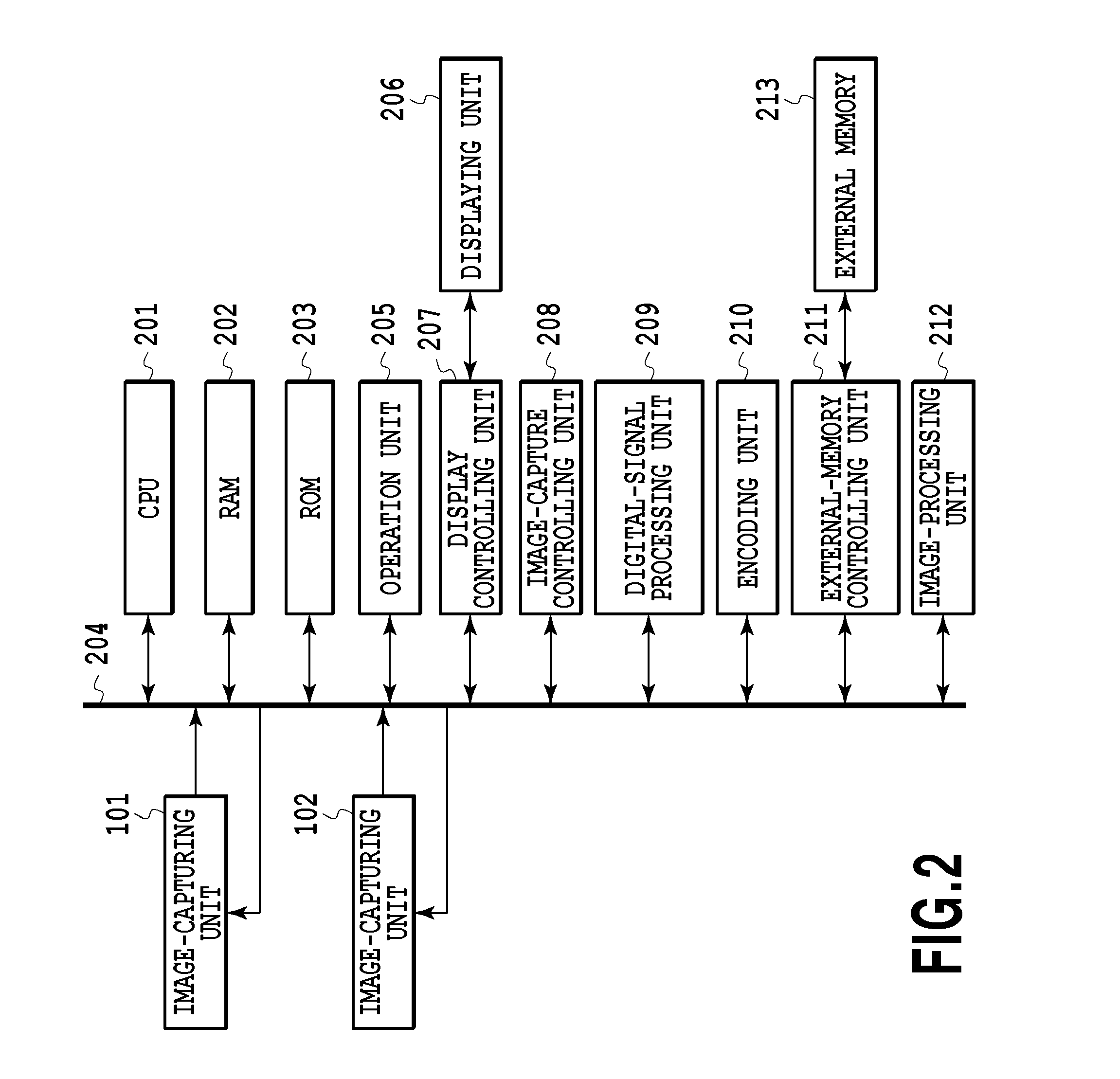
[0031]FIGS. 1A and 1B are diagrams showing an example of a multiple-point-of-view image-capturing apparatus according to a mul...
embodiment 2
[0077]In Embodiment 1, the virtual-angle-of-view image data 407 is generated by using any one of the weighting methods shown in FIGS. 7A to 7C. In Embodiment 2, the weighting method is switched according to a mode selected by the user. In this way, virtual-angle-of-view image data 407 based on a given image-capturing mode can be generated.
[0078]In Embodiment 2, the image-capture mode can be switched between a noise-reduction priority mode and a resolution priority mode. The mode can be switched by a user operation obtained from an operation unit 205. An example of weights in each mode will be described below. In the noise-reduction priority mode, the weights shown in FIG. 7A or 7B are used to perform image combination. In the resolution priority mode, the weights shown in FIG. 7C are used to perform image combination. Thus, in the noise-reduction priority mode, a captured image I1 and a captured image I2 are averaged, so that a noise reduction effect can be achieved. Moreover, in th...
embodiment 3
[0080]In Embodiment 1 and Embodiment 2, the virtual-angle-of-view image data 407 is generated by using a set of weights w1, w2 for the entire image. In Embodiment 3, the weights w1, w2 are corrected based on the difference between the image data on a captured image I1 and a captured image I2 which is calculated for each divided area, and the virtual-angle-of-view image data 407 is generated by using sets of weights differing from one area to another. In this way, it is possible to suppress deterioration in perceived resolution resulting from alignment errors.
[0081]Specifically, first, a virtual-angle-of-view image represented by the virtual-angle-of-view image data 407 is divided into a plurality of rectangular areas. Then, for each of these rectangular areas, the sum of the absolute values of the differences between the pixels (x,y) of the captured image I1 and the corresponding pixels (x′,y′) of the captured image I2 is calculated. Thereafter, a correction process is performed on ...
PUM
 Abstract
Description
Claims
Application Information
 - R&D
- Intellectual Property
- Life Sciences
- Materials
- Tech Scout
- Unparalleled Data Quality
- Higher Quality Content
- 60% Fewer Hallucinations
Browse by: Latest US Patents, China's latest patents, Technical Efficacy Thesaurus, Application Domain, Technology Topic, Popular Technical Reports.
© 2025 PatSnap. All rights reserved.Legal|Privacy policy|Modern Slavery Act Transparency Statement|Sitemap|About US| Contact US: help@patsnap.com


