Load cell having an elastic body

a technology of load cell and elastic body, which is applied in the field of load cell, can solve the problems of increasing the dimensions, affecting reducing the accuracy of load cell, so as to achieve easy and efficient manufacturing and marketing, and low manufacturing cost. , the effect of low price of sal

Active Publication Date: 2016-09-13
EILERSEN NILS AAGE JUUL
View PDF16 Cites 2 Cited by
  • Summary
  • Abstract
  • Description
  • Claims
  • Application Information

AI Technical Summary

Benefits of technology

[0019]According to the invention, this object is achieved by providing a precision load cell comprising an elastic body where the elastic body comprises a first beam and a second beam that is positioned opposite to the first beam, a base end and a load receiving end that is positioned opposite the base end where the first and the second beams are connected to the base end and to the load receiving end via flexure points that provide sections for elastic deformation, and a sealed cavity comprising a flexible wall and sensor means for measuring the elastic deformation of the elastic body in response to the load to be measured with the sealed cavity placed in the first beam and / or the second beam with the flexible wall and sensor means placed in the body of the beam between the flexure points of the beam. The precision load cell further comprising a lever having a first end and a second end, where the first end is connected to the flexible wall of the sealed cavity and the second end is connected to one or more of the opposite beam, the base end or the load receiving end, in order to transform any relative movement of the second ends of the lever into deformations of the flexible wall in response to the load to be measured. This way and according to the invention the load to be measured, may be measured by various types of sensor means placed in a sealed cavity, which because of a limited geometry and close thermal coupling of the walls provides a fast and nearly complete temperature equalization of the elastic body around the sealed cavity. Furthermore the thermal insulation between the beams and the base end and the load receiving end provided by the flexure points of the beams, limits influx of heat into the sealed cavity and the sensor means. The low strains in the solid walls each side of the sealed cavity placed in a beam provides very low changes of the deformation of the flexible wall of the sealed cavity under varying eccentricity of the load. With the sealed cavity and the sensor means placed in a beam between flexure points no influence on the measurement is seen when tightening the screws for mounting the solid base end and solid load receiving end in an application of the load cell.
[0041]An even further object of the present invention is to provide a new and improved load cell having an elastic body that has a low cost of manufacture with regard to both materials and labor, and which accordingly is then susceptible of low prices of sale to the consuming public, thereby making such load cell having an elastic body economically available to the buying public.

Problems solved by technology

The load cell, according to the patent EP1451538 does in practice display some problems.
One problem arises from temperature induced distortions of the walls of the sealed cavity for example when the rays of the sun shines on one of the walls, increasing the dimensions of this wall and hereby distorting the sealed cavity and influencing the sensor means, which give a transient shift of the zero.
A further problem is the temperature rise above ambient temperature of the sensor means, caused by the power generated by the electronic signal processing circuits, which normally are mounted in the base end of the load cell near the sensor means.
This temperature rise is difficult to compensate for in the zero and slope of the signals of the load cell as it is added to the temperature of the environment.
Another problem is the changing distortion of the cavity and the sensor means through a changing eccentricity of the loads applied on the load cell, which changes the forces in the two beams of the parallelogram.
This changing deformation of the walls of the sealed cavity, with changing eccentricity of the applied loads reduces the obtainable accuracies of the load cell.
Still another problem is the distortion of the sealed cavity and the sensor means when the mounting screws in the base end are tightened for mounting the load cell.
Load cells according to these patents do both display a problem common to this type of load cell where strain gages are applied to the flexure points of the parallelogram.
Inaccuracies in the strain gages themselves and in the bonding of the strain gages will however result in measurement errors with changing eccentricity of the load applied to the load cell, and these errors are tedious and time consuming to correct with filing or grinding of the flexure points.

Method used


Image

  • Load cell having an elastic body
  • Load cell having an elastic body
  • Load cell having an elastic body

Examples


Embodiment Construction

[0057]Referring now to the drawings, and particularly to FIGS. 1-10B, an embodiment of the load cell having an elastic body of the present invention will be described.

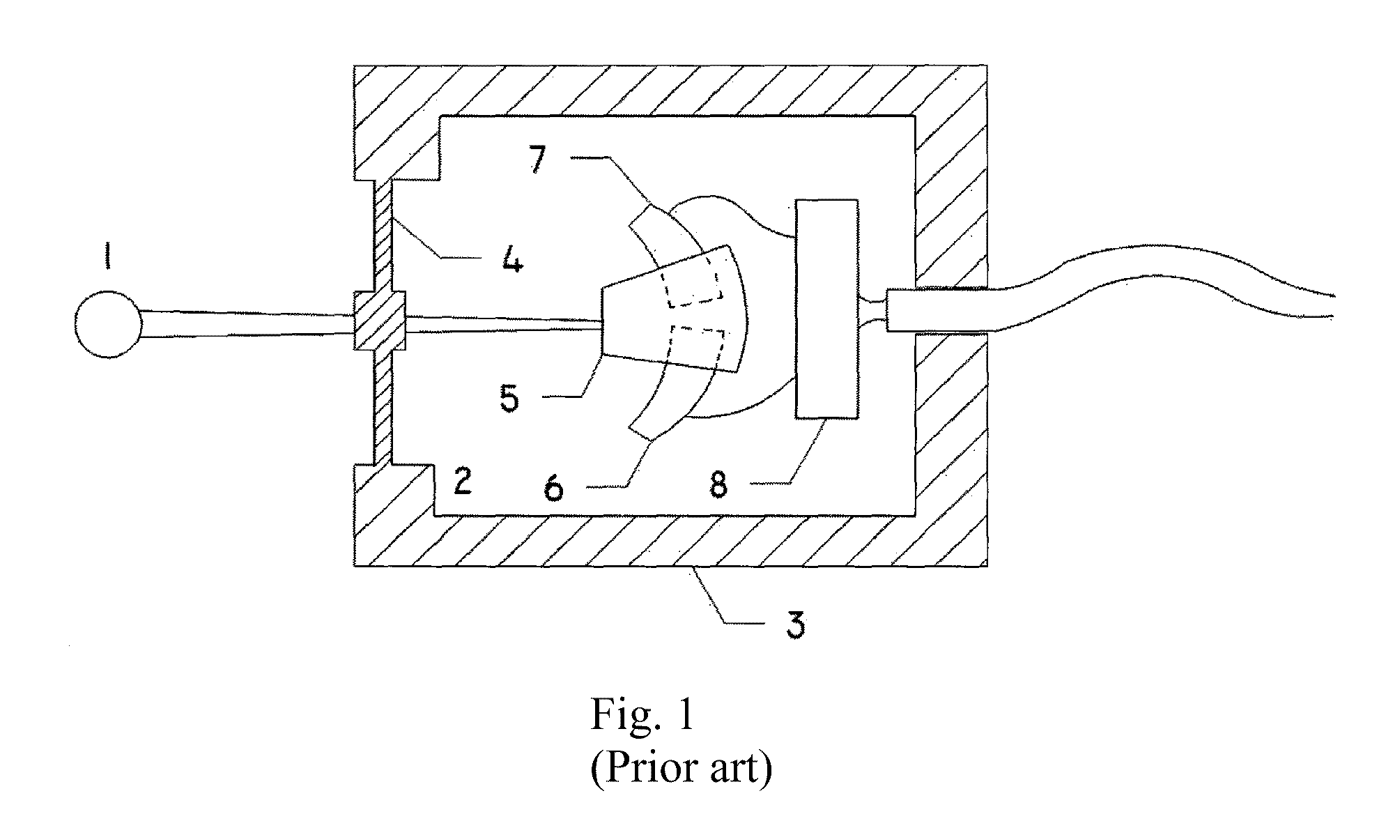
[0058]The sensor in FIG. 1 shows, as prior art, a simple sensor where the lever 1, is protruding into the sealed cavity 2, placed in the sensor body 3, through the flexible elastic wall 4, for activating the capacitive sensor means, by moving the grounded vane 5, in relation to the capacitance sensors 6 and 7 when the lever 1 is activated. The capacitance sensors 6 and 7 are connected to the capacitance measuring circuit 8.

[0059]This type of sensor, with different sensor means, is widely used as a joy stick for controlling machinery and the flexible wall protects the sensor means from humidity and corrosion in machinery in tough environments.

[0060]It is easily seen that a sensor according to FIG. 1 is quite unsuitable as a load cell because the forces for activating the sensor means are dependent on the length of the l...


PUM

PropertyMeasurementUnit
elastic deformationaaaaaaaaaa
flexibleaaaaaaaaaa
humidityaaaaaaaaaa

Abstract

An elastic body load cell including a first beam and a second beam opposite the first beam, a base end and a load receiving end positioned opposite the base end. The first and second beams are connected to the base end and to the load receiving end via flexure points providing elastic deformation sections. A cavity comprising a flexible wall and sensor means is defined in the first and / or second beams with the flexible wall and sensor means placed between the flexure points. The sensor means measures elastic deformation of the elastic body in response to a load. The load cell further includes a lever having a first end connected to the flexible wall, and a second end connected to the opposite beam, the base end or the load receiving end, to transform movement of the second end into deformations of the flexible wall in response to the load.

Description

CROSS-REFERENCE TO RELATED APPLICATION[0001]This application is a continuation application under 35 U.S.C. §120 based upon co-pending International Application Serial No. PCT / DK2014 / 000058 filed on Dec. 4, 2014. Additionally, this continuation application claims the benefit of priority under 35 U.S.C. §365(c) of International Application No. PCT / DK2014 / 000058 filed on Dec. 4, 2014. The entire disclosure of the prior application is incorporated herein by reference.BACKGROUND OF THE INVENTION[0002]1. Field of the Invention[0003]The present invention relates to load cells for measuring loads, comprising an elastic body fitted with sensor means to detect the strain or the deformation of the elastic body in response to the load to be measured.[0004]The invention relates more specifically to a precision load cell comprising an elastic body where the elastic body comprises a first beam and a second beam that is positioned opposite to the first beam, a base end and a load receiving end that...

Claims


Application Information

Patent Timeline
Patent Type & Authority Patents(United States)
IPC IPC(8): G01L1/22G01L1/00G01L1/14G01L1/04G01L1/24
CPCG01L1/142G01L1/14G01L1/22G01L1/24G01L5/223G01L1/2243G01L1/2281
Inventor EILERSEN, NILS AAGE JUUL
Owner EILERSEN NILS AAGE JUUL
Why Eureka
Try Eureka