Fixed radial anode drum dryer

a dryer and radial anode technology, applied in the direction of drying, lighting and heating equipment, furniture, etc., can solve the problems of energy to be dissipated, microwave induced ion rotation is not as efficient at causing the heating effect,

Active Publication Date: 2016-09-20
LG ELECTRONICS INC
View PDF86 Cites 30 Cited by
  • Summary
  • Abstract
  • Description
  • Claims
  • Application Information

AI Technical Summary

Problems solved by technology

A changing electric field across the dielectric material (in this case, a load of clothes) causes energy to be dissipated as the molecules attempt to line up with the continuously changing electric field, creating friction.
However, microwave induced ion rotation is not as efficient at causing the heating effects as the lower RF frequency fields that depend on slower molecular motion, such as those caused by ion drag.

Method used


Image

  • Fixed radial anode drum dryer
  • Fixed radial anode drum dryer
  • Fixed radial anode drum dryer

Examples


Embodiment Construction

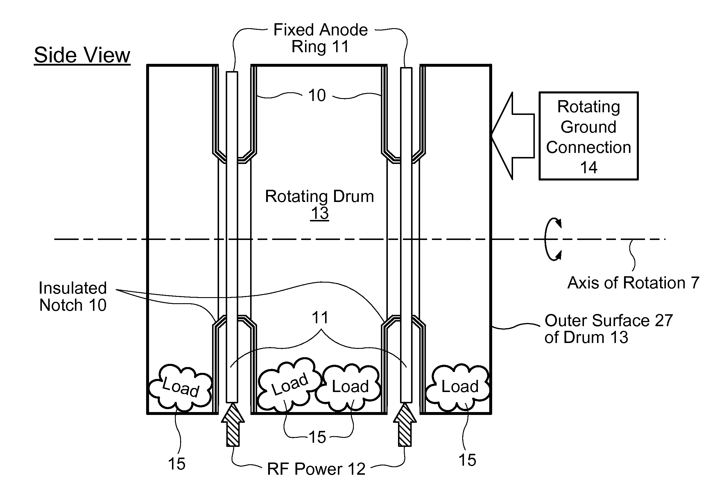
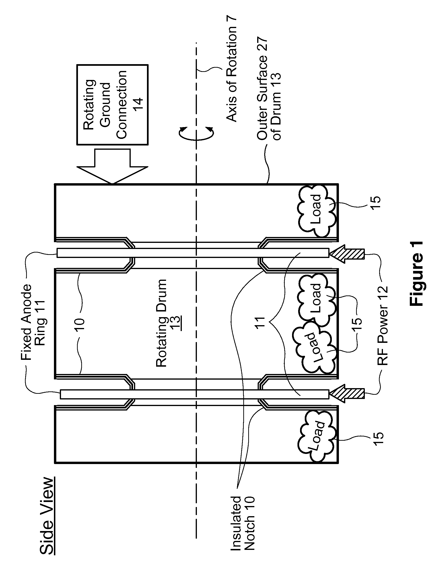
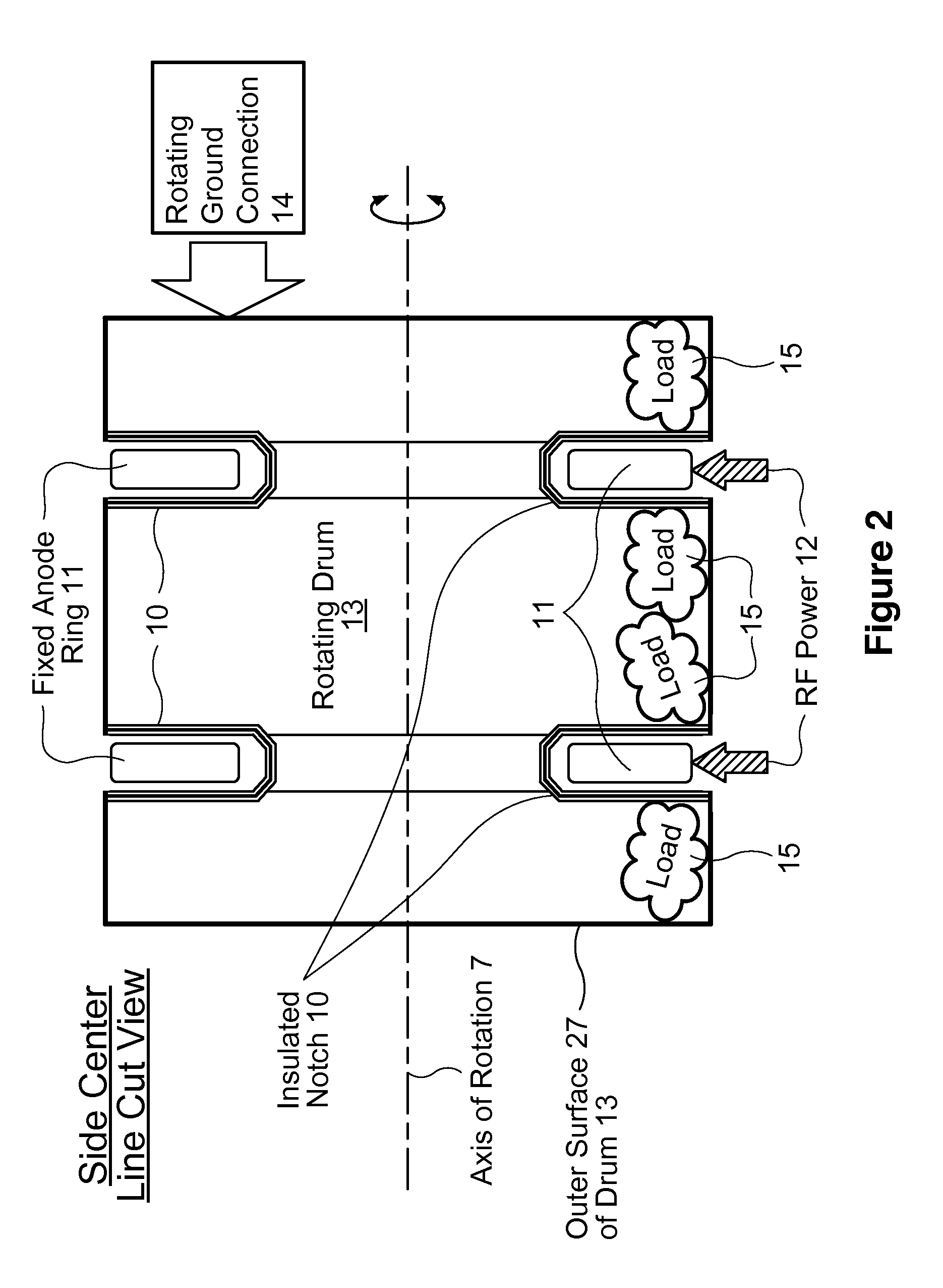
[0021]This invention comprises a rotating drum 13 that acts as a cathode of a large capacitor, with simplified connections to the one or more anodes 11 that produce an electric field inside the drum 13. The anodes 11 are spatially fixed, are mounted outside the hollow interior of the drum 13, and protrude into one or more notches 10 that are fabricated as indentations as part of the drum periphery 27. Anodes 11 maintain the necessary electric field contact with a load 15 of clothes inside the rotating drum 13, to effect optimum RF capacitive coupling. The minimization of parasitic capacitance from the anode 11 (where RF is applied) to the cathode drum 13 (which is grounded) is important for energy conversion efficiency when using the present invention's relatively low RF frequency. For this reason, it is desirable for the clothes 15 to be close to both the cathode 13 and to the anode(s) 11. In this patent application, parasitic capacitance is defined as any capacitance between the a...


PUM


Abstract

A clothes dryer apparatus (99) comprising an electrically conductive, grounded, generally cylindrical rotatable drum (13) having a hollow interior adapted to contain a load (15) of wet clothes to be dried. The drum's (13) exterior surface (27) is partially indented to form one or more integral, generally ring-shaped insulated notches (10). An electrically conductive, generally flat arcuate anode (11) is positioned within each notch (10), with no physical contact between an anode (11) and its corresponding notch (10). Each anode (11) is spatially fixed with respect to the rotatable drum (13), and is electrically isolated from conductive portions of the drum (13). A source (21) of RF power (12), operating at a single fixed frequency, is coupled to each anode (11).

Description

RELATED APPLICATIONS[0001]This patent application claims the priority benefit of commonly owned U.S. provisional patent application Ser. No. 62 / 123,274 filed Nov. 12, 2014; said U.S. provisional patent application and U.S. patent application Ser. No. 13 / 297,282 filed Nov. 16, 2011 and published as US 2013 / 0119055 A1 on May 16, 2013 are hereby incorporated by reference into the present patent application in their entireties.TECHNICAL FIELD[0002]This invention pertains to the field of drying a load of clothes using dielectric heating.BACKGROUND ART[0003]Dielectric heating involves the heating of materials by dielectric loss. A changing electric field across the dielectric material (in this case, a load of clothes) causes energy to be dissipated as the molecules attempt to line up with the continuously changing electric field, creating friction. This changing electric field may be caused by an electromagnetic wave propagating in free space as in a microwave oven, or it may be caused by...

Claims


Application Information

Patent Timeline
Patent Type & Authority Patents(United States)
IPC IPC(8): F26B3/34D06F58/26H05B6/54D06F58/04H05B6/62
CPCD06F58/266D06F58/04F26B3/343H05B6/62F26B3/34
Inventor WISHERD, DAVID S.EISENBERG, JOHN ALANWOHL, MICHAEL ANDREWD'ANNA, PABLO EUGENIO
Owner LG ELECTRONICS INC
Why Eureka
Try Eureka