Segmented mirror apparatus for imaging and method of using the same

a segmented mirror and optical technology, applied in the field of optical apparatus, can solve the problems of self-weight distortion, large mirror thickness, and significant increase in production cost, and achieve the effects of less surface distortion, easy mounting, and convenient handling during testing

Active Publication Date: 2016-09-20
KLA CORP
View PDF155 Cites 5 Cited by
  • Summary
  • Abstract
  • Description
  • Claims
  • Application Information

AI Technical Summary

Benefits of technology

[0008]A general object of the invention is to replace one large parent mirror with a plurality of smaller mirror segments. These mirrors are lighter and easier to mount. In addition, small mirrors have less surface distortion due to mounting and self-weight. Smaller mirror segments are easier to handle during testing and require fewer test points.
[0009]Another object of the invention is to use identical mirror segments when the parent mirror is spherical. Using identical mirror segments to form a spherical shape reduces manufacturing complexity. If the parent mirror is ashperical, each mirror segment could be a best fit sphere close enough to the parent asphere that the combination of the spheres will not degrade the image quality unacceptably.

Problems solved by technology

The sheer size of the mirror significantly increases the cost of production.
Moreover, large mirrors require an increased thickness to reduce self-weight distortion, which adds to the overall cost of production.
Adding a graduated or indexed coating to a large mirror adds complexity to the manufacturing process.
Large mirrors are more expensive and difficult to test.
Moreover, numerous test points are required for large mirrors due to the number of small sub-apertures.
This additional testing requires more labor and time to validate the mirror.
Rework can be a continual process, which impacts yield and cost.

Method used


Image

  • Segmented mirror apparatus for imaging and method of using the same
  • Segmented mirror apparatus for imaging and method of using the same
  • Segmented mirror apparatus for imaging and method of using the same

Examples


Embodiment Construction

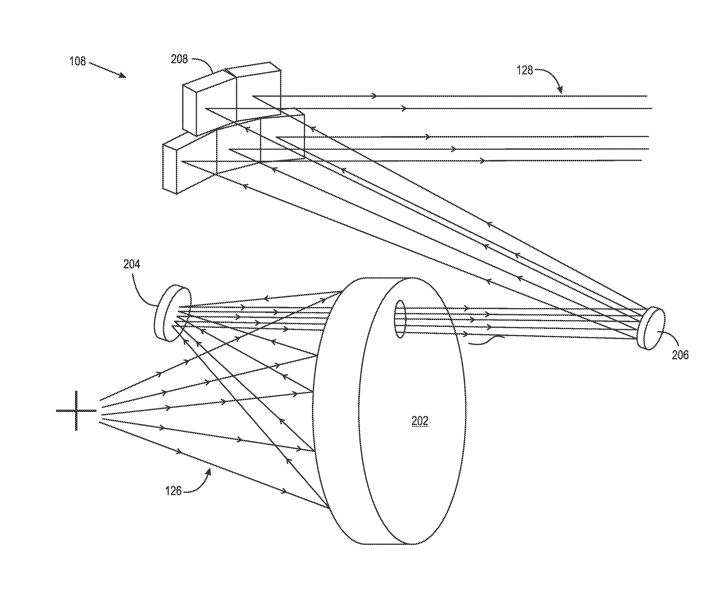
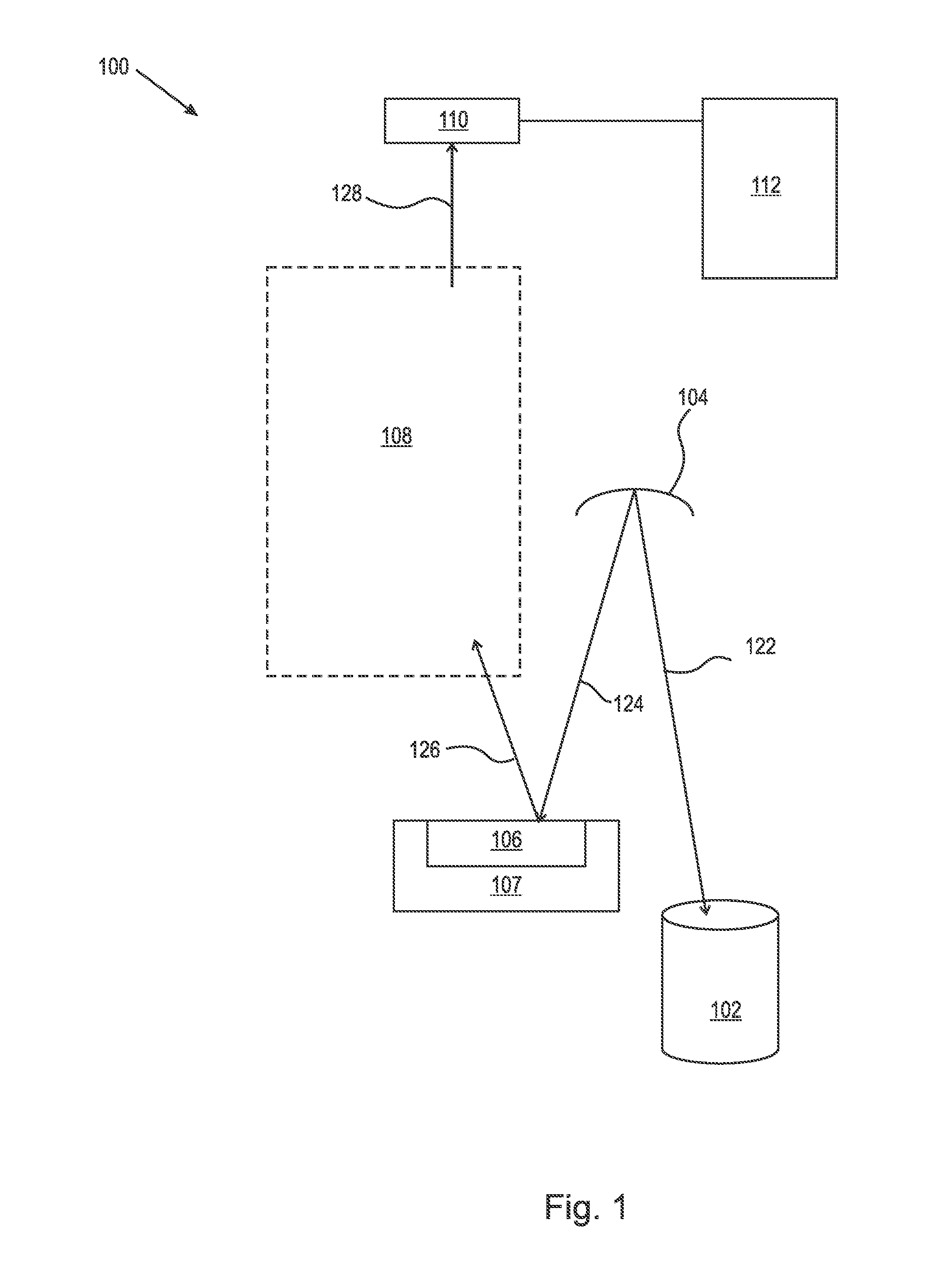
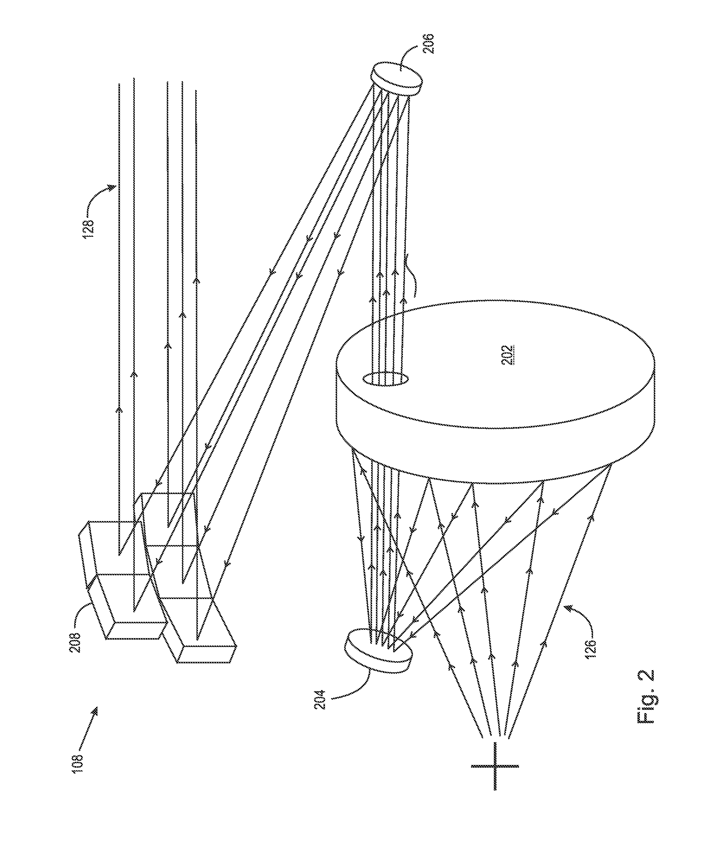
[0016]At the outset, it should be appreciated that like drawing numbers on different drawing views identify identical, or functionally similar, structural elements of the invention. It also should be appreciated that figure proportions and angles are not always to scale in order to clearly portray the attributes of the present invention.

[0017]While the present invention is described with respect to what is presently considered to be the preferred aspects, it is to be understood that the invention as claimed is not limited to the disclosed aspects. The present invention is intended to cover various modifications and equivalent arrangements included within the spirit and scope of the appended claims.

[0018]Furthermore, it is understood that this invention is not limited to the particular methodology, materials and modifications described and, as such, may, of course, vary. It is also understood that the terminology used herein is for the purpose of describing particular aspects only, a...


PUM

PropertyMeasurementUnit
distanceaaaaaaaaaa
wavelengthsaaaaaaaaaa
feature sizesaaaaaaaaaa

Abstract

An apparatus for inspecting a photomask, comprising an illumination source for generating a light which illuminates a target substrate, objective optics for receiving and projecting the light which is reflected from the target substrate, the objective optics includes a first mirror arranged to receive and reflect the light which is reflected from the target substrate, a second mirror which is arranged to receive and reflect the light which is reflected by the first mirror, a third mirror which is arranged to receive and reflect the light which is reflected by the second mirror, and a segmented mirror which is arranged to receive and reflect the light which is reflected by the third mirror. The segmented mirror includes at least two mirror segments. The apparatus further includes at least one sensor for detecting the light which is projected by the objective optics.

Description

FIELD OF THE INVENTION[0001]The present invention broadly relates to optical apparatus and methods of using the same, and, more particularly, to an optical apparatus having a segmented mirror for imaging and, even more particularly, to an optical apparatus and method for inspecting a photomask using light imaging.BACKGROUND OF THE INVENTION[0002]The conventional apparatus in the market for photomask inspection generally employ ultra-violet (UV) light with wavelengths at or above 193 nanometers (nm). This is suitable for masks designed for use in lithography based on 193 nm light. To further improve the printing of minimum feature sizes, next generation lithographic equipment is now designed for operation in the neighborhood of 13.5 nm. Accordingly, patterned masks designed for operation near 13 nm must be inspected. Such masks are reflective, having a patterned absorber layer over a resonantly-reflecting substrate (EUV multilayer), typically 40 pairs of molybdenum silicide (MoSi) wi...

Claims


Application Information

Patent Timeline
Patent Type & Authority Patents(United States)
IPC IPC(8): G01N21/88G03F1/84G02B5/09G02B5/08G01N21/956
CPCG02B5/0891G01N21/8806G02B5/09G03F1/84G01N21/956
Inventor KVAMME, DAMONCHILESE, FRANK
Owner KLA CORP
Why Eureka
Try Eureka