
System and method for three dimensional calibration of force plates

a technology of force plate and three-dimensional calibration, which is applied in the field of system and a method for three-dimensional calibration of force plate, can solve the problems of considerable error in assumption and may also be in error in considering, and achieve the effect of improving the accuracy of force plate measuremen

Active Publication Date: 2016-10-04
ADVANCED MECHANICAL TECH
View PDF13 Cites 5 Cited by
  • Summary
  • Abstract
  • Description
  • Claims
  • Application Information

AI Technical Summary

Benefits of technology

[0007]The present invention addresses the force plate calibration problem and provides a system and a method for calibrating a force plate with improved accuracy.
[0014]Among the advantages of this invention may be one or more of the following. The calibration process of this invention improves the accuracy of the force platform measurements, as shown in FIG. 12A-FIG. 12F. The typical cross talk error is in the order of ±0.01% of the applied load, and the typical load error is less than 0.001 or ±0.1% of applied load. The average Center of Pressure (COP) error is typically less than 0.2 mm.

Problems solved by technology

This assumption is considerably in error for our Hall effect platforms which have different z offsets for x and y axes.
This assumption may also be in error when considering cross talk effects.

Method used


Image

  • System and method for three dimensional calibration of force plates
  • System and method for three dimensional calibration of force plates
  • System and method for three dimensional calibration of force plates

Examples


Embodiment Construction

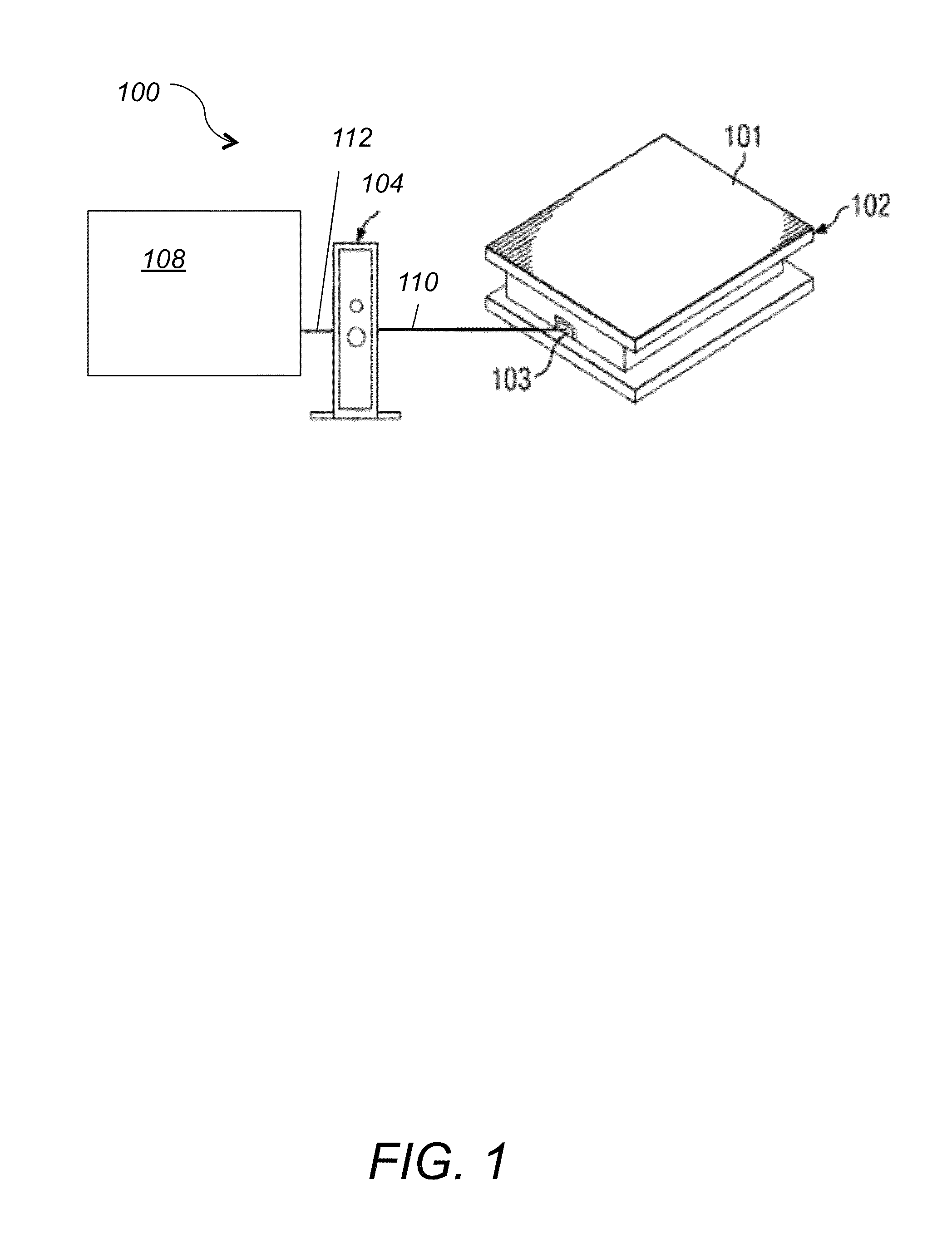
[0036]FIG. 1 is an illustration of a force platform system 100 according to an embodiment of the invention. System 100 is used to measure ground reaction forces and includes a force platform 102, a signal conditioner 104, and a computer 108 used for data collection. The system may include more than one force platforms, and / or signal conditioners. Signal conditioner 104 may be an analog amplifier and / or digital processor, and may be connected to or embedded in the force plate. Computer 108 may be a personal computer (PC), a server, a mobile computing device or a computing circuit.

[0037]Force platform 102 shown in FIG. 1 is designed to measure the forces and moments applied to its top surface 101 as a subject stands, steps, or jumps on it. Force platform 102 outputs force signals to output port 103, where platform 102 can connect to and communicate with force signal conditioner 104.

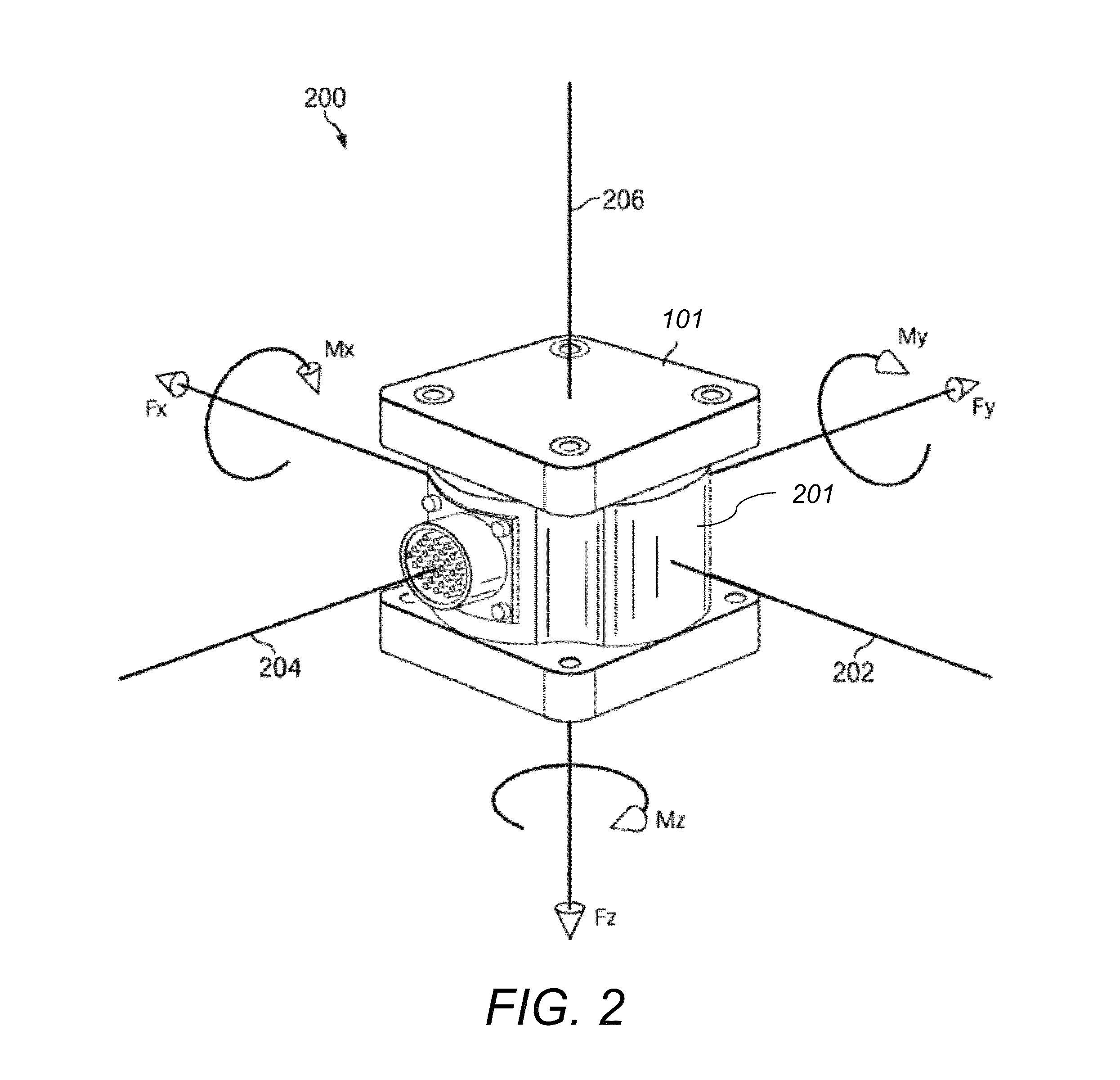
[0038]Force platform 102 includes one or more force transducers or load cells for measuring forces. FIG....


PUM

PropertyMeasurementUnit
weightsaaaaaaaaaa
weightsaaaaaaaaaa
weightsaaaaaaaaaa

Abstract

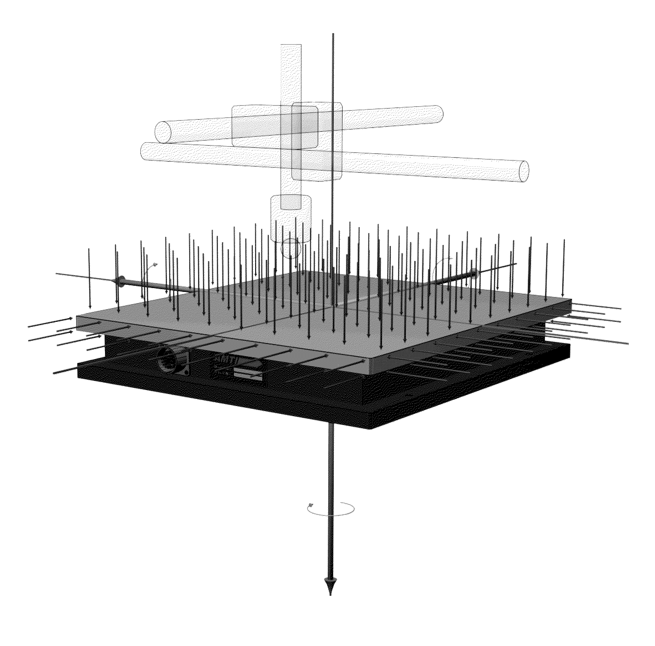
A method for calibrating a force platform includes, providing a force platform and applying an n×m grid on a top surface of the force platform via a computing device. Next, applying p known loads on each of the n×m grid points of the top surface along a Z-axis being perpendicular to the X and Y axes and along the X and Y axes. Next, taking multipoint measurements at each grid point and for each applied known load along the X, Y and Z axes and generating six measured output signals, exact position coordinates and applied known load magnitude for each grid point. Next, assembling an array of n×m×p of six equations with six unknown for each grid point and applied known load and then solving the assembled equations and deriving a position and load specific calibration matrix for each grid point.

Description

CROSS REFERENCE TO RELATED CO-PENDING APPLICATIONS[0001]This application is a continuation in part and claims the benefit of U.S. application Ser. No. 13 / 273,864 filed on Oct. 14, 2011 and entitled FORCE PLATFORM SYSTEM which is commonly assigned and the contents of which are expressly incorporated herein by reference.FIELD OF THE INVENTION[0002]The present invention relates to a system and a method for three dimensional calibration of force plates, and more particularly to a three dimensional calibration of force plates that provides improved measurement accuracy and reduction of crosstalk errors.BACKGROUND OF THE INVENTION[0003]A force platform is a measuring device that measures ground reaction forces. Typically force platforms are mounted in a pit so that their top surface lies flush with the floor. Subjects are then instructed to walk across or stand on the platforms and the generated ground reaction forces are recorded. Force platforms are commonly used for research and clinic...

Claims


Application Information

Patent Timeline
Patent Type & Authority Patents(United States)
IPC IPC(8): G01L25/00A61B5/00A61B5/103G01L5/16G01G23/01A61B5/11
CPCG01L25/00A61B5/1036A61B5/1038A61B5/112A61B5/4023A61B5/6887A61B5/7235G01G23/01G01L5/16A61B5/1116A61B2560/0223A61B2562/0247
Inventor WHITE, BRUCE F.RULAND, FREDCARIGNAN, FOREST J.DRUEDING, ALBERTGLASS, GARYTAYLOR, JONATHAN
Owner ADVANCED MECHANICAL TECH
Learn More