
Generation of azimuthally or radially polarized radiation in optical waveguides

a technology of azimuthally or radially polarized radiation and optical waveguide, which is applied in the direction of optical waveguide light guide, optical element, instrument, etc., can solve the problem of very small wavelength difference between the modes in practice, and achieve the effect of simple, stable and cost-effectiv

Inactive Publication Date: 2016-10-04
FRAUNHOFER GESELLSCHAFT ZUR FOERDERUNG DER ANGEWANDTEN FORSCHUNG EV +1
View PDF8 Cites 0 Cited by
  • Summary
  • Abstract
  • Description
  • Claims
  • Application Information

AI Technical Summary

Benefits of technology

The present invention provides a simple, stable, and cost-effective radiation source that generates azimuthally or radially polarized radiation. The device can easily change between these polarization modes with a simple thermal or mechanical adjustment to the grating. This is a significant improvement over previous methods that required major expenditures and special components. Additionally, the reflexion properties of the grating can be influenced through heating or cooling, or by applying a mechanical force, allowing for a more flexible and efficient use of the device.

Problems solved by technology

However, the wavelength difference between the modes in practice is very small.

Method used


Image

  • Generation of azimuthally or radially polarized radiation in optical waveguides
  • Generation of azimuthally or radially polarized radiation in optical waveguides
  • Generation of azimuthally or radially polarized radiation in optical waveguides

Examples


Embodiment Construction

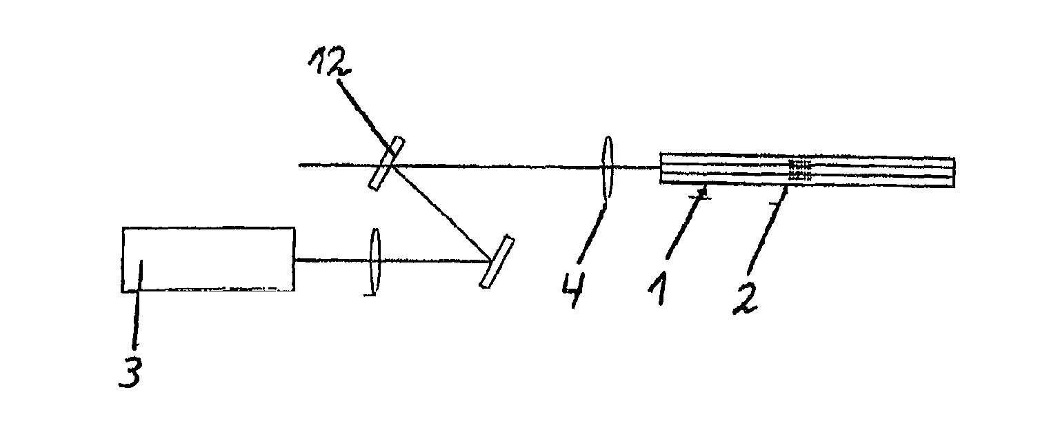
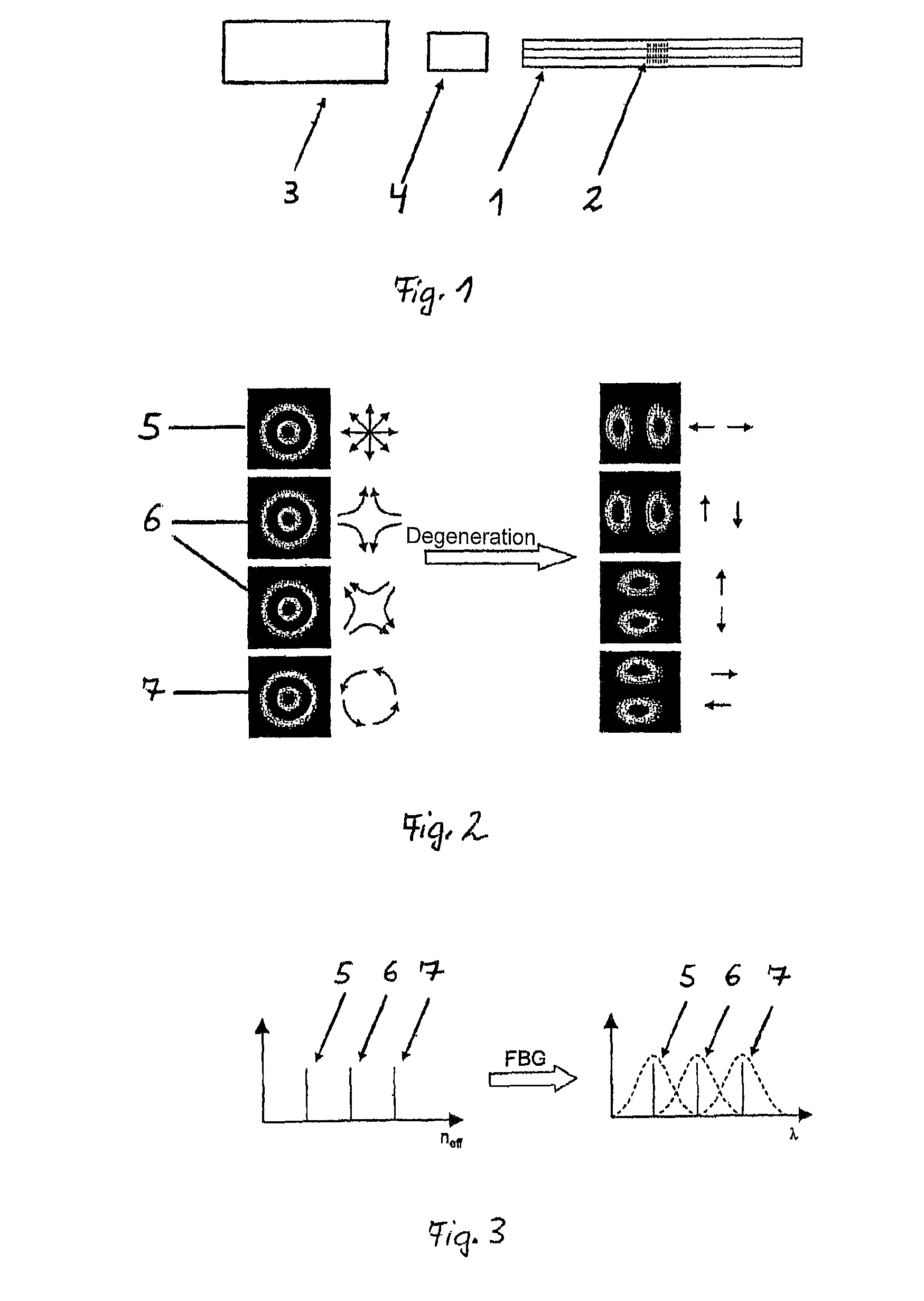
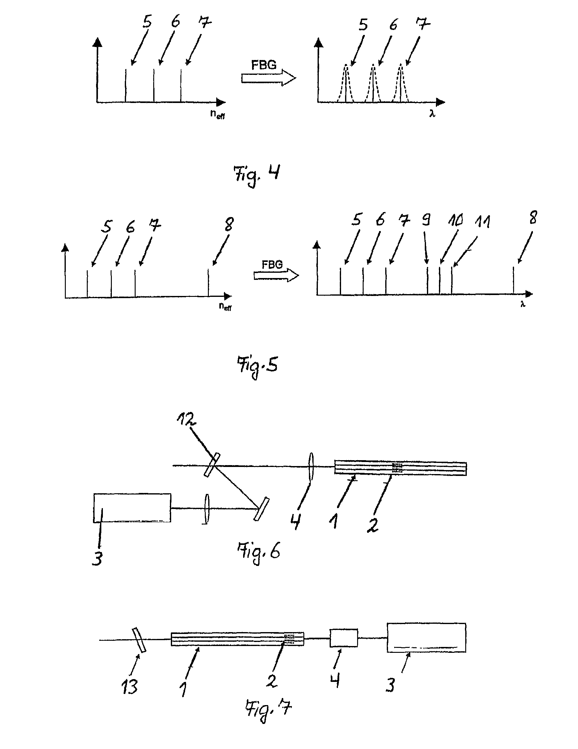
[0028]The inventive device shown in FIG. 1 consists of an optical waveguide 1, a fibre Bragg grating 2, a light source 3, and an optical probe 4.

[0029]In accordance with the invention, the structure of the optical waveguide 1 must be so designed that it abolishes the degeneration of the modes, i.e. it is “strongly conducting”. Hereby, the azimuthally or radially polarized modes obtain different refractive indices. The modes conducted within the optical waveguide 1 are reflected at the fibre Bragg grating 2, wherein the difference between the effective refractive indices of the modes is converted into a difference of the reflexion wavelength. Since the wavelength difference between the modes is relatively small, the fibre Bragg grating 2 must be designed to be sufficiently narrow-band in order to achieve high polarization purity of the modes. If the fibre Bragg grating 2 is too broadband, the reflected modes overlap each other and polarization purity drops.

[0030]FIG. 2 shows a radial...


PUM


Abstract

The invention relates to an apparatus for generating azimuthally or radially polarized radiation by means of an optical waveguide (1), wherein the optical waveguide (1) has a structure which is suitable for conducting azimuthally or radially polarized modes (5, 7). The invention proposes that the azimuthally or radially polarized modes (5, 7) in the optical waveguide (1) have different effective refractive indices and, within the optical waveguide (1), a narrow-band grating (2) is arranged, in particular a fiber Bragg grating (2) which is designed such that the spectral distance between two azimuthally or radially polarized resonant modes (5, 7) is equal to or greater than the associated spectral bandwidth.

Description

CROSS REFERENCE TO RELATED APPLICATIONS[0001]This application is the National Stage of PCT / EP2011 / 001881 filed on Apr. 14, 2011, the disclosure of which is incorporated by reference. The international application under PCT article 21(2) was not published in English.BACKGROUND OF THE INVENTION[0002]1. Field of the Invention[0003]The invention relates to an apparatus for generating azimuthally or radially polarized radiation by means of an optical waveguide, wherein the optical waveguide has a structure which is suitable for conducting azimuthally or radially polarized modes.[0004]2. The Prior Art[0005]Devices which emit radially or azimuthally polarized radiation are of great interest for a multitude of applications in the field of science, medical technology, military technology or civil engineering, for example for material machining, microscopy or for so-called optical tweezers, too. These applications call for light sources with azimuthally or radially polarized radiation, in par...

Claims


Application Information

Patent Timeline
IPC IPC(8): G02B6/10H01S3/067H01S3/08G02B27/28
CPCG02B6/105H01S3/0675H01S3/06712G02B27/286H01S3/0804
Inventor TUENNERMANN, ANDREASJOCHER, CHRISTOPHJAUREGUI MISAS, CESARLIMPERT, JENS
Owner FRAUNHOFER GESELLSCHAFT ZUR FOERDERUNG DER ANGEWANDTEN FORSCHUNG EV
Learn More