Method and arrangement for remotely driving light emitting diodes from a three-phase power source via a single phase cable system

a technology of light-emitting diodes and remote driving, which is applied in the direction of electroluminescent light sources, semiconductor lamp usage, electric lighting sources, etc., can solve the problems of complex and bulky circuits of ac-dc drivers such as the one, and the life of such circuits is usually limited

Active Publication Date: 2016-10-04
HUIZHOU LIGHT ENGINE LTD
View PDF14 Cites 1 Cited by
  • Summary
  • Abstract
  • Description
  • Claims
  • Application Information

AI Technical Summary

Benefits of technology

[0009]To further improve regulation and efficiency of such three-phase-driven LED lighting, in a preferred embodiment the driving circuitry embodies commutating constant current sources.
[0010]The use of such commutating constant current sources for driving LEDs in a series-connected string minimizes the ripple in the drive voltage that is “seen” by the LEDs, thereby reducing the off-time and causing no notable flicker in the emitted light. Compared to conventional power supplies, the size of such three-phase power supply can be much smaller. There is no electromagnetic interference filter in the circuit. Reliability will be higher since no electrolytic capacitor is used in the circuit. The circuit is more environmental-friendly because significantly fewer components are used. The circuit is especially cost effective for high wattage power supplies us used in public urea lighting, warehouses, agriculture, etc.

Problems solved by technology

AC-DC drivers such as the one shown in FIG. 1 are complex and bulky circuits.
The lifetime of such circuits is usually limited by the electrolytic capacitors used in such circuits.
A disadvantage of such products, however, is that the AC line voltage is sinusodal, and low-frequency AC LED systems conventionally operate in a rectified mode, that causes the AC-driven LED to be turned off and on at a rate that is double the line frequency. FIG. 2A schematically illustrates such a known AC-driven LED.
This percentage or off-time may, under some circumstances, be noticed by an observer as a flicker and can be a drawback to the acceptability of LED lighting by certain consumers.

Method used


Image

  • Method and arrangement for remotely driving light emitting diodes from a three-phase power source via a single phase cable system
  • Method and arrangement for remotely driving light emitting diodes from a three-phase power source via a single phase cable system
  • Method and arrangement for remotely driving light emitting diodes from a three-phase power source via a single phase cable system

Examples


Embodiment Construction

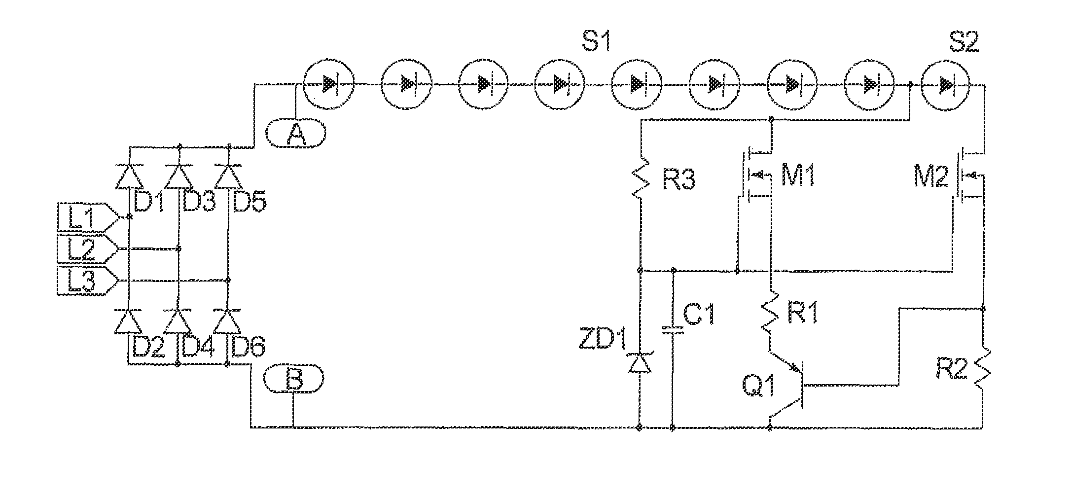
[0033]FIG. 3 is a circuit diagram of a first embodiment of three-phase LED driving circuitry in accordance with the present invention. Diodes D1 through D6 form a three-phase rectifier, connected to inputs at which the three phases L1, L2 and L3 from a three-phase power source are supplied to the driving circuitry. The three-phase rectifier formed by the diodes D1 through D6 converts in the incoming signals L1, L2, and L3 into a DC voltage, which is applied across a string S1 of light emitting diodes. A resistor R1 limits the current through the LED string S1.

[0034]The light output from the LEDs in FIG. 3 is shown as a waveform in FIG. 4. As can be seen from FIG. 4, there is no off-time. Instead, them is a ripple at a rate of six times the line frequency. In most countries, this flicker is at 300 or 360 Hz, which theoretically cannot be perceived. The efficiency of the circuit shown in FIG. 3 is approximately 85%. Because only the resistor R1 is used to limit the current to the LED ...


PUM


Abstract

Multiple LEDs connected in series are driven by DC voltage that is provided by a diode rectifier connected to a three-phase power source. In order to reduce ripple in the DC voltage, the series-connected LEDs can be divided into a first set and a second set, and a first constant current source is provided that drives the first set, and a second constant current source is provided that drives the second set. The first and second constant current sources are both connected across the outputs of the rectifier circuit, and operate to drive the respective sets of light emitting diodes in alternation. The capability for dimming can be provided, as well as back-up single phase operation. The light emitting diodes can be situated remote from said rectifier and connected thereto by a single phase power transmission system, formed by only two wires.

Description

TECHNICAL FIELD OF THE INVENTION[0001]The present invention relates to driving circuitry and driving methods for operating light emitting diodes (LEDs).BACKGROUND OF THE INVENTION[0002]Typically, the use of LEDs as an AC powered light source requires a driver to convert AC line power to a regulated DC power for maintaining constant light output. Such an LED driver is a self-contained power supply that has output matched to the electrical characteristics, such as forward voltage and driving current, of the LED. Usually, the driver is built on an individual PCB and connects to an LED PCB which contains the array of LEDs.[0003]FIG. 1 shows typical circuitry of an AC-DC LED driver using the known flyback converter topology. The circuitry 10 includes an AC power source 12 with live (L) and neutral (N) terminals, and a rectifier circuit 14 that converts the AC, e.g., sinusoidal, input waveform to a DC waveform, e.g., a half wave rectified waveform. The circuit operates such that when the ...

Claims


Application Information

Patent Timeline
Patent Type & Authority Patents(United States)
IPC IPC(8): H05B33/08H05B44/00
CPCH05B33/0845H05B33/0815H05B45/48Y02B20/30H05B45/10
Inventor LO, CHUNG PING KEVINLEUNG, WA HINGSIU, KAM WAH
Owner HUIZHOU LIGHT ENGINE LTD
Why Eureka
Try Eureka