Gate driving circuit and display device using the same

a driving circuit and display device technology, applied in the field of display devices, can solve the problems of increasing the number of tfts, difficult to reduce the bezels surrounding the display panel, and so as to reduce the ripples in the gate signal and delay the degradation of tfts

Active Publication Date: 2022-03-01
LG DISPLAY CO LTD
View PDF13 Cites 0 Cited by
  • Summary
  • Abstract
  • Description
  • Claims
  • Application Information

AI Technical Summary

Benefits of technology

[0011]The present disclosure is directed to solve the problem above, and is to provide a gate driving circuit capable of reducing ripples in a gate output signal.
[0012]In addition, the present disclosure is to provide a gate driving circuit using a smaller number of TFTs and using TFTs with a smaller size when TFTs are added for the purpose of minimizing ripples.
[0013]Further, the present disclosure is to provide a gate driving circuit preventing TFTs from being influenced by DC stress.
[0017]The output unit outputs a gate pulse by charging the output terminal from bootstrapping the Q node and maintain the output terminal at the low level voltage according to the QB node voltage that swings between high level and low level voltages. Also, the output unit may maintain the output terminal at the low level voltage according to a second clock lagging the first clock by four horizontal periods (4H). Also, the output unit may suppress the ripples generated at the output terminal by using the low level voltage of the first clock.
[0019]Therefore, ripples in a gate signal may be reduced while a smaller number of TFTs are employed to construct a switch circuit. Also, bezels can be made slim by forming a switch circuit with small-sized TFTs. Also, by implementing the TFTs for discharging output terminals to operate in an alternating manner, the TFTs may be prevented from being subjected to DC stress, and degradation of the TFTs may be delayed.

Problems solved by technology

If the simple GIP circuit drives a landscape panel the length along the horizontal direction of which is larger than the length along the vertical direction, gate lines are coupled to data lines, causing ripples in gate signals.
However, this approach increases the number of TFTs constituting a switch circuit for charging and discharging the voltages of a Q node and a QB node that are used to control the pull-up TFTs and the pull-down TFTs, respectively.
These all together make it difficult to reduce the bezels surrounding a display panel.
Also, by implementing the TFTs for discharging output terminals to operate in an alternating manner, the TFTs may be prevented from being subjected to DC stress, and degradation of the TFTs may be delayed.

Method used


Image

  • Gate driving circuit and display device using the same
  • Gate driving circuit and display device using the same
  • Gate driving circuit and display device using the same

Examples


Embodiment Construction

[0037]A display device of the present disclosure may be implemented by using a flat panel display device such as a liquid crystal display (LCD), field emission display (FED), plasma display panel (PDP), organic light emitting display (OLED), or electrophoretic display (EPD).

[0038]In what follows, various aspects of the present disclosure will be described in detail with reference to appended drawings. Throughout the specification, the same numbers actually refer to the same elements. In describing the present disclosure, a detailed description of known functions or configurations incorporated herein unnecessarily obscure the gist of the present disclosure, the detailed description thereof will be omitted.

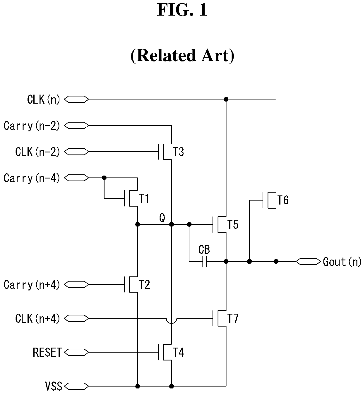
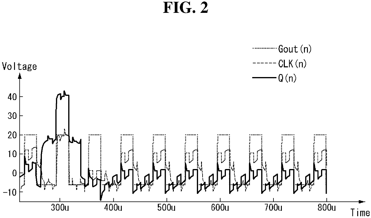
[0039]FIG. 1 illustrates a GIP circuit employing pull-up TFTs only according to the related art, and FIG. 2 illustrates an example in which ripples are generated in an output signal due to the GIP circuit of FIG. 1.

[0040]The GIP circuit of FIG. 1 includes seven TFTs and one bootstra...


PUM


Abstract

The present disclosure relates to a gate driving circuit and a display device using the circuit. A gate driving circuit according to an aspect of the present disclosure comprises a Q node controller, a QB node controller, and an output unit generating a pulse-type output signal by controlling charging and discharging of an output terminal according to the voltages of the Q node and the QB node, and the QB node controller controls the voltage of the QB node in an alternating manner during a non-scan period in which the Q node controller outputs a low level voltage for the Q node.

Description

BACKGROUNDField of the Disclosure[0001]The present disclosure relates to a display device, and more particularly, to a gate driving circuit and a display device using the same. Although the present disclosure has a wide scope of applications, it is particularly suitable for reducing ripples in a gate signal without enlarging a bezel area.Description of the Background[0002]Types of flat panel display devices include liquid crystal display (LCD), plasma display panel (PDP), organic light emitting diode (OLED), and electrophoretic display (EPS).[0003]A driving circuit of a display device includes a pixel array displaying an image, a data driving circuit providing data signals to data lines of the pixel array, a gate driving circuit (or scan driving circuit) providing a gate pulse (or scan pulse) synchronized with the data signal sequentially to gate lines (or scan lines) of the pixel array, and a timing controller controlling the data driving circuit and the gate driving circuit.[0004]...

Claims


Application Information

Patent Timeline
Patent Type & Authority Patents(United States)
IPC IPC(8): G11C19/00G09G3/36G09G3/3266G06F3/041G11C19/28
CPCG09G3/3677G06F3/0412G09G3/3266G09G3/3688G09G3/3696G11C19/28G09G2300/0408G09G2310/0286G09G2310/0291
Inventor KIM, YEONKYUNGMOON, TAEWOONGLEE, JUNGHYUN
Owner LG DISPLAY CO LTD
Why Eureka
Try Eureka