Method for minimizing LED flicker of an LED driver system

a technology of led driver and driver system, which is applied in the direction of electroluminescent light sources, semiconductor lamp usage, electric lighting sources, etc., can solve the problems of overheating hazards of the driver system, high cost, and inconvenience for the manufacturer, so as to minimize eliminate the flicker of led modules, and minimize the ripple of current flowing

Active Publication Date: 2016-11-15
CHIPONE TECH BEIJINGCO LTD
View PDF12 Cites 0 Cited by
  • Summary
  • Abstract
  • Description
  • Claims
  • Application Information

AI Technical Summary

Benefits of technology

[0013]One objective of the present invention is to disclose a method for minimizing LED flicker of an LED driver system, which is capable of automatically adjusting a regulation current of a current regulator to an average value of a full-wave-rectified output current of a PFC constant current converter, so as to minimize the ripple of a current flowing through an LED module and thereby eliminate the flicker of the LED module.
[0014]Another objective of the present invention is to disclose a method for minimizing LED flicker of an LED driver system, which is capable of making a regulation current equal to an average value of a full-wave-rectified output current of a PFC constant current converter without the need of using a precise current-setting resistor.
[0020]To make it easier for our examiner to understand the objective of the invention, its structure, innovative features, and performance, we use preferred embodiments together with the accompanying drawings for the detailed description of the invention.

Problems solved by technology

On the other hand, if the constant current set by the current regulator is lower than the constant average value of the output current IOUT, an excess current will flow through the capacitor 12 to lift up the level of the output voltage VOUT, which can result in an overheat hazard of the driver system.
However, as general resistors have a variance in resistance, the current-setting resistor 16 can therefore cause a mismatch between the constant current set by the current regulator and the constant average value of the output current IOUT, and thereby cause the problems mentioned above.
However, the cost will be much higher.
Besides, when a variety of different constant average values of the output current IOUT are required (so as to provide a dimming function, for example), the setting of the current regulator will have to be changed accordingly, which can cause much inconvenience to the manufacturer.

Method used


Image

  • Method for minimizing LED flicker of an LED driver system
  • Method for minimizing LED flicker of an LED driver system
  • Method for minimizing LED flicker of an LED driver system

Examples


Embodiment Construction

[0026]The present invention will be described in more detail hereinafter with reference to the accompanying drawings that show the preferred embodiments of the invention.

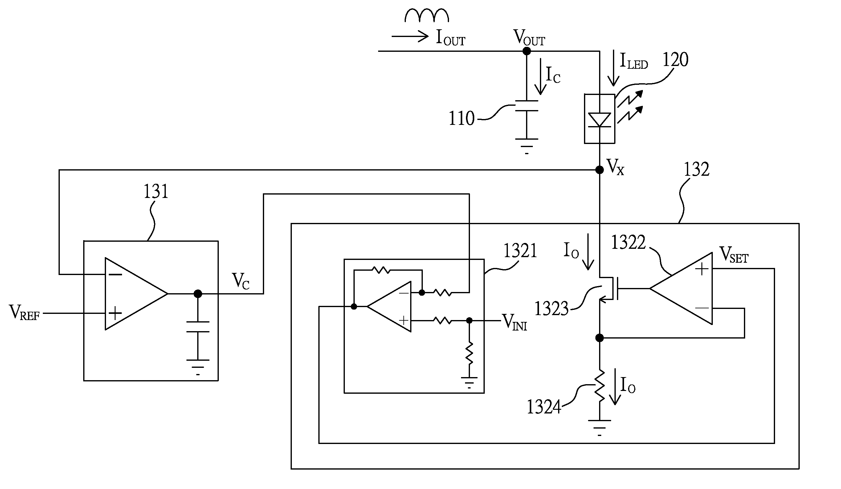
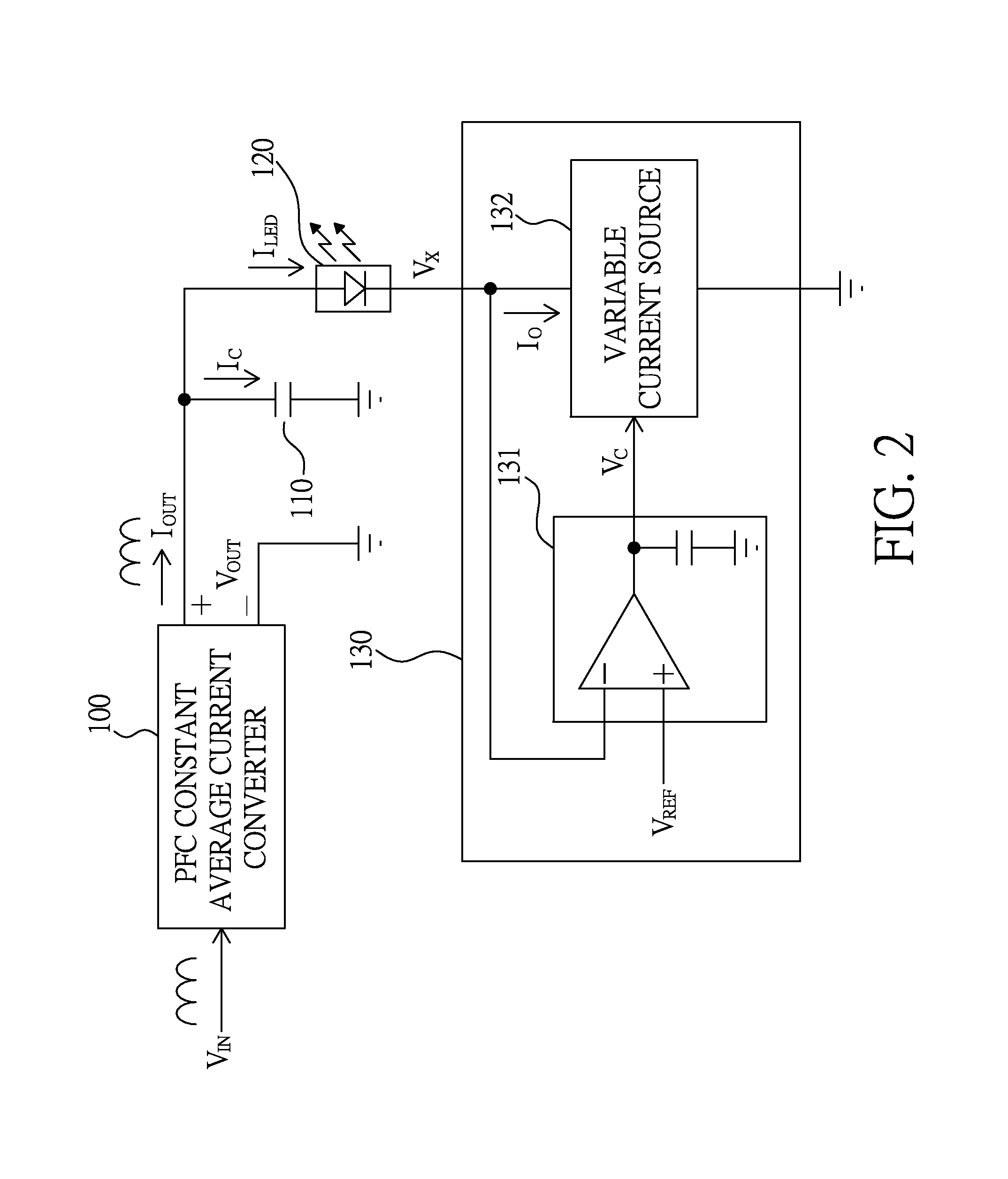
[0027]Please refer to FIG. 2, which illustrates a circuit diagram of an LED driver system using a flicker elimination method of the present invention. As illustrated in FIG. 2, the LED driver system includes a PFC constant average current converter 100, a capacitor 110, an LED module 120, and a current regulator 130.

[0028]The PFC constant average current converter 100 has an input coupled to a full-wave-rectified input voltage VIN and an output providing an output voltage VOUT and an output current IOUT, both the output voltage VOUT and the output current IOUT being in phase with the full-wave-rectified input voltage VIN, and the output current IOUT having a constant average value.

[0029]The capacitor 110 is coupled between the output of the PFC constant average current converter 100 and a ground to let a current IC ...


PUM


Abstract

A method for minimizing LED flicker of an LED driver system, the LED driver system comprising a PFC constant average current converter, a capacitor, an LED module, and a current regulator, the method including: a first step: the current regulator generating a control voltage according to an average of a difference between a reference voltage and a voltage at a second end of the LED module; and a second step: the current regulator determining a regulation value for a current flowing through the LED module according to the control voltage.

Description

BACKGROUND OF THE INVENTION[0001]Field of the Invention[0002]The present invention relates to an LED (light emitting diode) driving method, especially to a method for minimizing LED flicker of an LED driver system.[0003]Description of the Related Art[0004]Please refer to FIG. 1, which illustrates a circuit diagram of a prior art LED driver circuit. As illustrated in FIG. 1, the prior art LED driver circuit includes a bridge rectifier 10, a PFC constant average current converter 11, a capacitor 12, an LED module 13, an NMOS (n type metal oxide semiconductor) transistor 14, an amplifier 15, and a current-setting resistor 16.[0005]The bridge rectifier 10 is used to generate a full-wave-rectified voltage VIN according to an AC power VAC.[0006]The PFC (power factor correction) constant average current converter 11 is coupled with the bridge rectifier 10 to make an input current IIN in phase with the full-wave-rectified voltage VIN, and generate an output voltage VOUT and an output curren...

Claims


Application Information

Patent Timeline
Patent Type & Authority Patents(United States)
IPC IPC(8): H05B33/08H05B44/00
CPCH05B33/0845H05B33/0815H05B33/0824H05B33/0803H05B45/44H05B45/37H05B45/397Y02B20/30
Inventor WANG, YEN-HUIWANG, CHI-JUNG
Owner CHIPONE TECH BEIJINGCO LTD
Why Eureka
Try Eureka