Apparatus comprising a charge pump and LCD driver comprising such an apparatus

a charge pump and lcd driver technology, applied in pulse manipulation, pulse technique, instruments, etc., can solve the problems of difficult to develop optimal bias level generators, load of different voltage levels can become very unbalanced, and current consumption that is not negligibl

Inactive Publication Date: 2009-10-20
CALLAHAN CELLULAR L L C
View PDF3 Cites 1 Cited by
  • Summary
  • Abstract
  • Description
  • Claims
  • Application Information

AI Technical Summary

Benefits of technology

[0017]In a preferred embodiment of the invention the voltage levels are programmable.
[0018]Mainly, the invention has been developed to use on-chip stage capacitors for the charge pump and external, large value buffer capacitors in order to minimize the ripple of the outputs, but it is not limited to this embodiment. A charge pump may use also external stage capacitors instead of the on-chip stage capacitors. It is also possible to employ a combination of on-chip an external capacitors.
[0019]The invention is particularly well suited for any application requiring to supply several voltage levels, higher or lower than the input (supply) voltage, where each level is loaded differently in current.
[0020]Additional features and advantages of the invention will be set forth in the description that follows, and in part will be apparent from the description.

Problems solved by technology

LCD driving ICs implementing these driving schemes have, due to the switching, a current consumption that is not negligible.
Depending on the pattern displayed on the LCD panel, the loads of the different voltage levels can become very unbalanced (sometimes with a factor of 10).
Because of this highly random load distribution, it is very difficult to develop a bias level generator which is optimal.
With a capacitive voltage booster for instance, it is known that the higher a voltage is needed, the higher would be the current consumption.
Recent developments propose a solution that is not yet optimal.
The known approaches for providing a set of voltage levels are not satisfying if the load is unbalanced, for instance.

Method used


Image

  • Apparatus comprising a charge pump and LCD driver comprising such an apparatus
  • Apparatus comprising a charge pump and LCD driver comprising such an apparatus
  • Apparatus comprising a charge pump and LCD driver comprising such an apparatus

Examples


Embodiment Construction

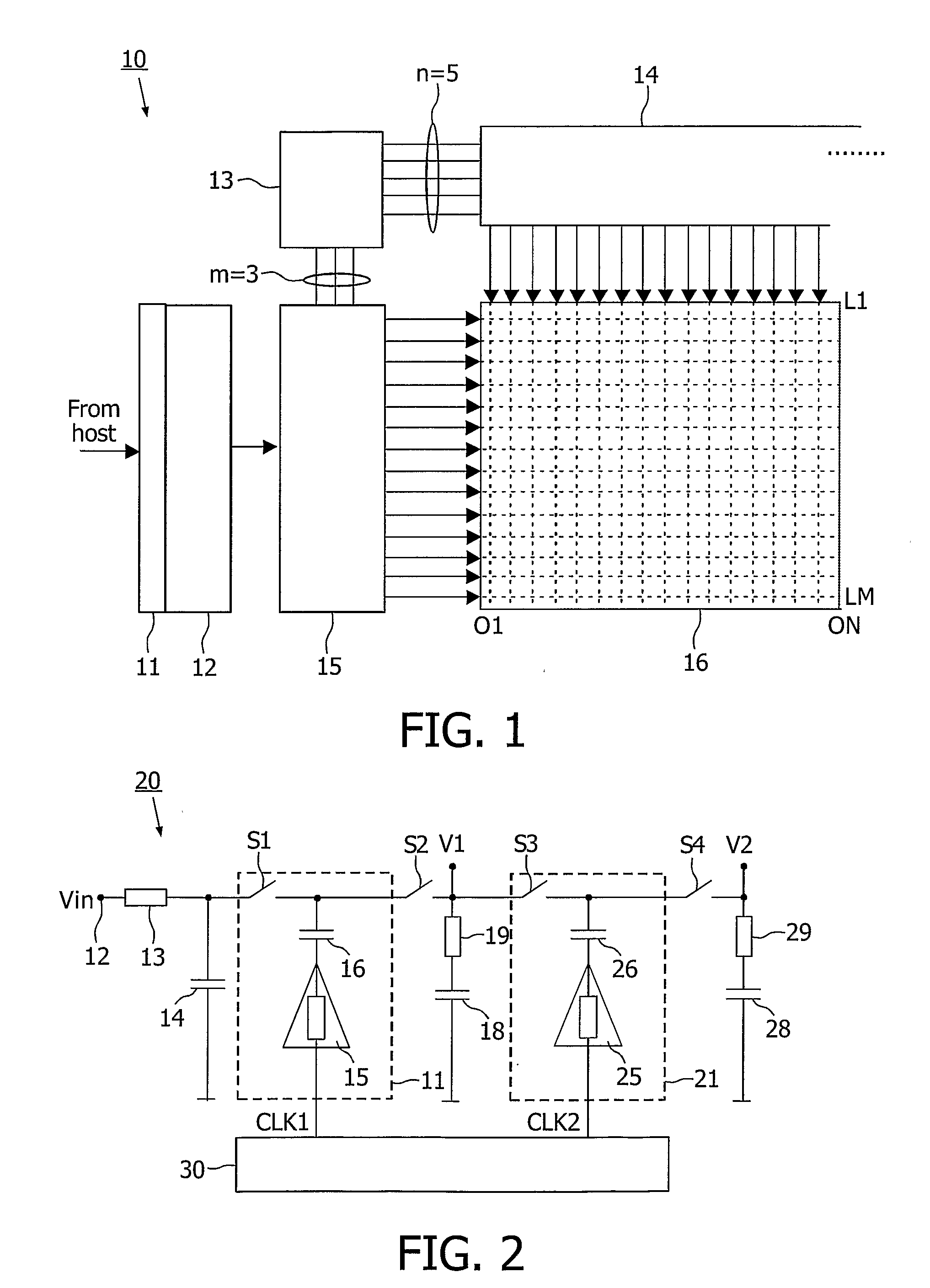
[0029]Before addressing detailed embodiments of the present invention, the typical block diagram of a LCD system 10 is addressed.

[0030]FIG. 1 shows a typical block diagram of a LCD system 10. A serial or a parallel interface is used as the interface between a host computer (not illustrated in FIG. 1) and a display module. A serial interface function 11 is typically integrated into a display timing controller 12. There is a column driver bank 14 driving the columns of a LCD display 16. The column driver bank 14 comprises a plurality of column drivers. Typically, each source driver of the column driver bank 14 serves n column electrodes (with n=288=96 RGB or 396=132 RGB, for example) of the display panel 16 by providing analog output signals (for example the 5 levels V2, V1, VC, MV1 and MV2). In the present example, each column driver serves one column electrode only. There is a row driver array 15 comprising an array of row drivers. In the most current application, a group of p=4 row...


PUM


Abstract

Apparatus comprising a charge pump (20) with multiple independently regulated outputs (V1, V2) for providing different voltage levels at each of said outputs. The charge pump (20) comprises a low voltage input (12), on / off regulation (30), and at least two charge stages (11, 21) which arc arranged in a cascaded manner. Each charge stage (11, 21) comprises a stage capacitor (16, 26), a switch (S1, S3), and a buffer (15, 25) for pumping a bottom plate of the stage capacitor (16, 26).

Description

FIELD OF THE INVENTION[0001]The present invention concerns charge pumps and systems, such as LCD drivers, based thereon.BACKGROUND OF THE INVENTION[0002]Charge pumps are used to generate a higher voltage than the supply voltages available for an application. For example, in a Liquid Crystal Display (LCD) driver, a charge pump is used to generate the bias voltages required by the driving schemes.[0003]In the LCD driving integrated circuits (ICs), the trend is nowadays for manufacturers to develop ever higher resolution and color displays for mobile terminals (phones, PDAs, etc.). These displays need a large current at a voltage approaching 20V, which has to be generated by the LCD driving IC. Charge pumps are used, with on-chip capacitors or with external capacitors, in order to achieve this voltage.[0004]A characteristic of modern driving schemes for passive liquid crystal displays (LCDs) is that several DC voltage levels are switched to supply the rows and columns of a matrix of pi...

Claims


Application Information

Patent Timeline
Patent Type & Authority Patents(United States)
IPC IPC(8): G05F1/10H02M3/07
CPCH02M3/07G09G3/20G09G3/36
Inventor NEGOI, ANDY
Owner CALLAHAN CELLULAR L L C
Why Eureka
Try Eureka