Implants and methods for using such implants to fill holes in bone tissue
a technology of bone tissue and implants, applied in the field of surgical implants, can solve the problems of not providing fixation of bone flaps to adjacent cranial bones, unable to induce tissue healing by using metal meshes, and rarely healing of bore holes, etc., to achieve the effect of improving mechanical properties, increasing combined bone growth, and high strength
- Summary
- Abstract
- Description
- Claims
- Application Information
AI Technical Summary
Benefits of technology
Problems solved by technology
Method used
Image
Examples
first embodiment
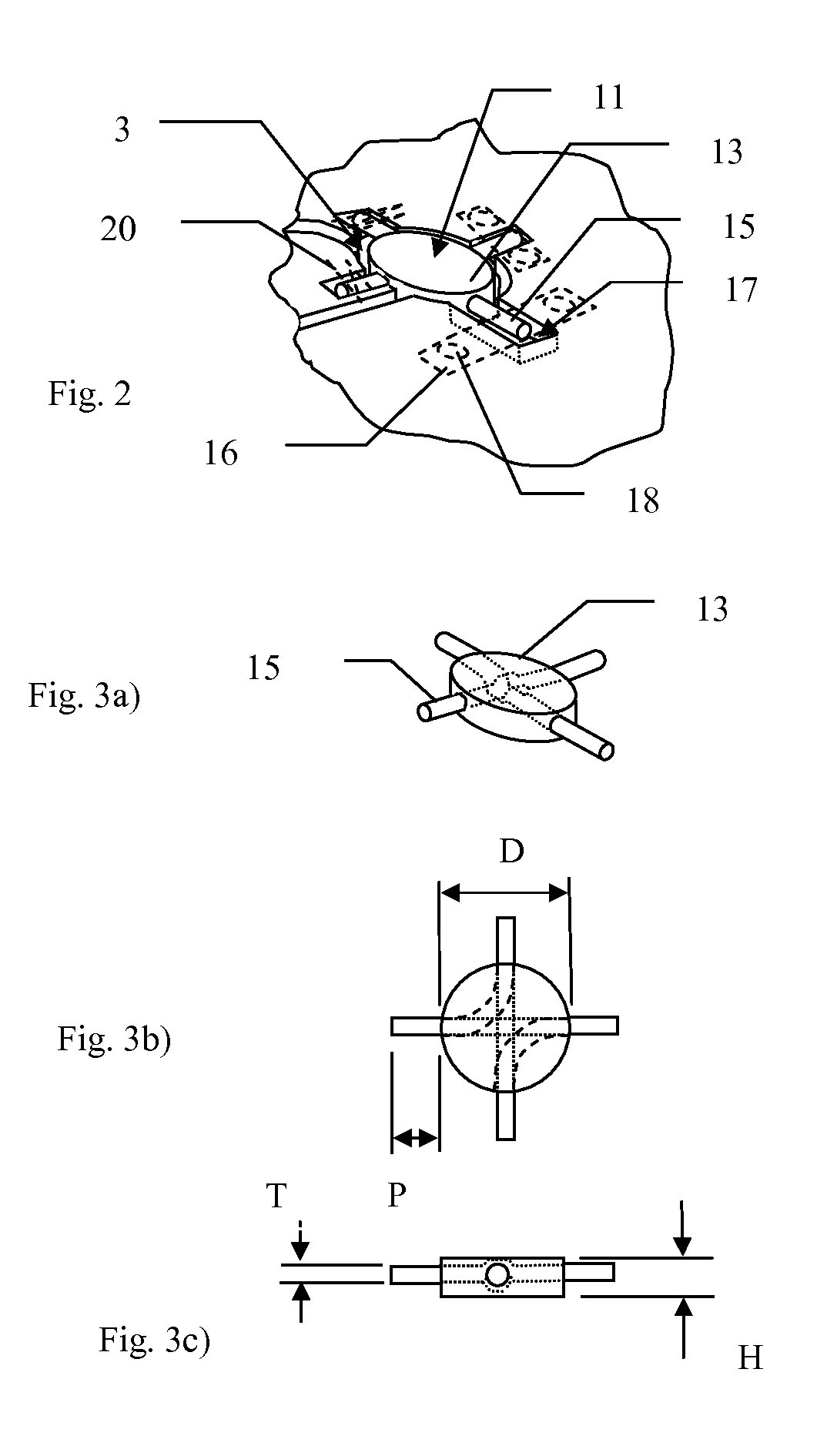
[0033]FIGS. 3a)-3c) shows schematically the implant 11 of FIG. 2 in perspective, plan and side views. Implant 11 has a circular body 13 of diameter D and height H. Preferably D is greater than H. Preferably D is between 8 and 20 mm, more preferably between 9 and 15 mm and even more preferably between 10 and 14 mm. Height H is preferably between 1 and 10 mm, more preferably between 2 and 8 mm and even more preferably between 3 and 6 mm. Protruding substantially radially from body 13 are anchoring wires 15. Each wire protrudes a distance P from body 13 and has a diameter T. Preferably the length of protrusion P is between 2 and 15 mm, more preferably between 3 and 10 mm and even more preferably between 4 and 8 mm. The diameter T of each wire is preferably less than 3 mm, more preferably less than 2 mm and most preferably 1 mm or less. In this example of the invention there are four anchoring wires 15 made from two lengths of wire which cross inside the tile as shown by dotted lines in...
second embodiment
[0034]FIGS. 4 and 5a)-5c) show schematically the present invention in which each anchoring wire 415 extending from the body 413 of the implant 411 is provided with a substantially circular anchoring tile 419 at its distal end. Each anchoring tile has a diameter d and a height h. Preferably d is between 2 and 10 mm, more preferably between 3 and 8 mm and even more preferably between 4 and 6 mm. Height h is preferably between 0.5 and 6 mm, more preferably between 1 and 5 mm and even more preferably between 1.5 and 4 mm. The anchoring tile is intended to be positioned in an anchoring chamber 421 formed at the end of each of the anchoring grooves 417. Preferably d is less than D and h is less than H in order to minimise the amount of material which has to be removed to form anchoring chambers. The arms and / or anchoring tiles are each retained in their grooves by retaining means—not shown—for example via plates and screws and / or clamps and / or sutures or any other fixing means.
third embodiment
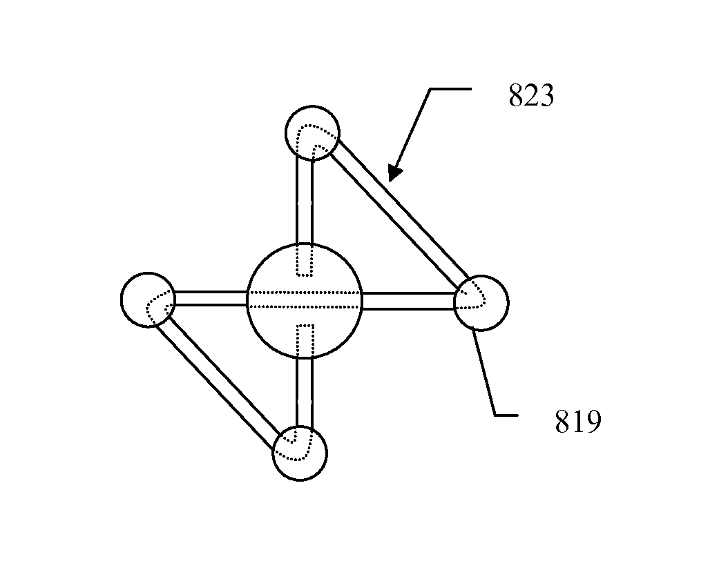
[0035]FIGS. 6 and 7a)-7c) show schematically the present invention in which the anchoring wire 615 of the implant 611 forms one or more closed loops 623 protruding from the body 613 of the implant. As can be seen in FIG. 7b) a single anchoring wire is formed into a figure of eight shape with its ends almost meeting at the centre of the figure of eight shape. The body 613 of the implant is formed over these ends. The closed loops extend a distance E from the body 613. Preferably E is between 5 and 15 mm, more preferably between 6 and 12 mm and even more preferably between 8 and 10 mm. The anchoring loops are intended to be positioned in suitably formed anchoring grooves 617 which extend from a bore hole 603 and then return to the same bore hole. The arms are each retained in their grooves by retaining means—shown by dashed lines, for example via plates 616 and screws 618 and / or clamps and / or sutures 620 or any other fixing means.
PUM
| Property | Measurement | Unit |
|---|---|---|
| width | aaaaa | aaaaa |
| width | aaaaa | aaaaa |
| width | aaaaa | aaaaa |
Abstract
Description
Claims
Application Information
 - R&D
- Intellectual Property
- Life Sciences
- Materials
- Tech Scout
- Unparalleled Data Quality
- Higher Quality Content
- 60% Fewer Hallucinations
Browse by: Latest US Patents, China's latest patents, Technical Efficacy Thesaurus, Application Domain, Technology Topic, Popular Technical Reports.
© 2025 PatSnap. All rights reserved.Legal|Privacy policy|Modern Slavery Act Transparency Statement|Sitemap|About US| Contact US: help@patsnap.com


