Implants and methods for using such implants to fill holes in bone tissue

a technology of bone tissue and implants, applied in the field of surgical implants, can solve the problems of not providing fixation of bone flaps to adjacent cranial bones, unable to induce tissue healing by using metal meshes, and rarely healing of bore holes, etc., to achieve the effect of improving mechanical properties, increasing combined bone growth, and high strength

Active Publication Date: 2013-02-28
OSSDSIGN
View PDF5 Cites 31 Cited by
  • Summary
  • Abstract
  • Description
  • Claims
  • Application Information

AI Technical Summary

Benefits of technology

[0004]The present invention describes a implant (an implant is a kind of medical device made to replace and act as a missing biological structure), which can be used as a biomedical implant and which combines a wire or mesh anchoring system (a wire anchoring system comprises a plurality of wires, preferably crossing wires, where none of the wires are joined to each other while a mesh comprises at least two crossing wires joined at some or all of their intersections) and a biomaterial mosaic element which provides increased combined bone in-growth and better mechanical properties compared to prior art systems. A biomaterial is any matter, surface, or construct that interacts with biological systems. The implant comprises a mosaic element that combines at least one flexible high strength wire or mesh with at least one mosaic tile. The invention can be employed as a replacement for the bone removed by drilling during craniotomy. The biomedical implant can be composed of resorbable biomaterials and / or stable biomaterials such as polymers, ceramics and metals. Preferably the implant is osteo-conductive (i.e. can serve as a scaffold on which bone cells can attach, migrate, and grow and divide) or osteo-inductive (i.e. can serve to induce new bone formation), and has high mechanical strength. This is satisfied by an implant system that combines a anchoring system (for example one or more wires) with a solid biomaterial tile—the implant body. Preferably the anchoring system is made of a biomaterial. This system has the beneficial effects of mechanically strong anchoring system (e.g. a wire) and an osteo-conductive and / or osteo-inductive solid implant (e.g. made of a ceramic material). The implant system can be easily attached to a skull in the operation room. The anchoring system may be attached to adjacent cranial bone and a bone flap by screws. Alternatively the anchoring system may use anchoring channels formed in the skull and or bone flap which are positioned to receive the wires. Combinations of screws and anchoring channels are also possible. The solid implant body, which preferably is moulded onto the wire or wires during manufacturing of the implant, is preferably composed of an osteo-conductive and / or osteo-inductive material that facilitates bone in-growth onto the implant system.

Problems solved by technology

At the end of the procedure the bone flap is replace and reattached to the skull, however the bore holes seldom heal and provide no protection to the underlying brain.
Current strategies using metal mesh do not induce tissue healing.
Currently used ceramics are utilized only to provide osteoconductive support but will not provide fixation of the bone flap to adjacent cranial bone.

Method used


Image

  • Implants and methods for using such implants to fill holes in bone tissue
  • Implants and methods for using such implants to fill holes in bone tissue
  • Implants and methods for using such implants to fill holes in bone tissue

Examples


first embodiment

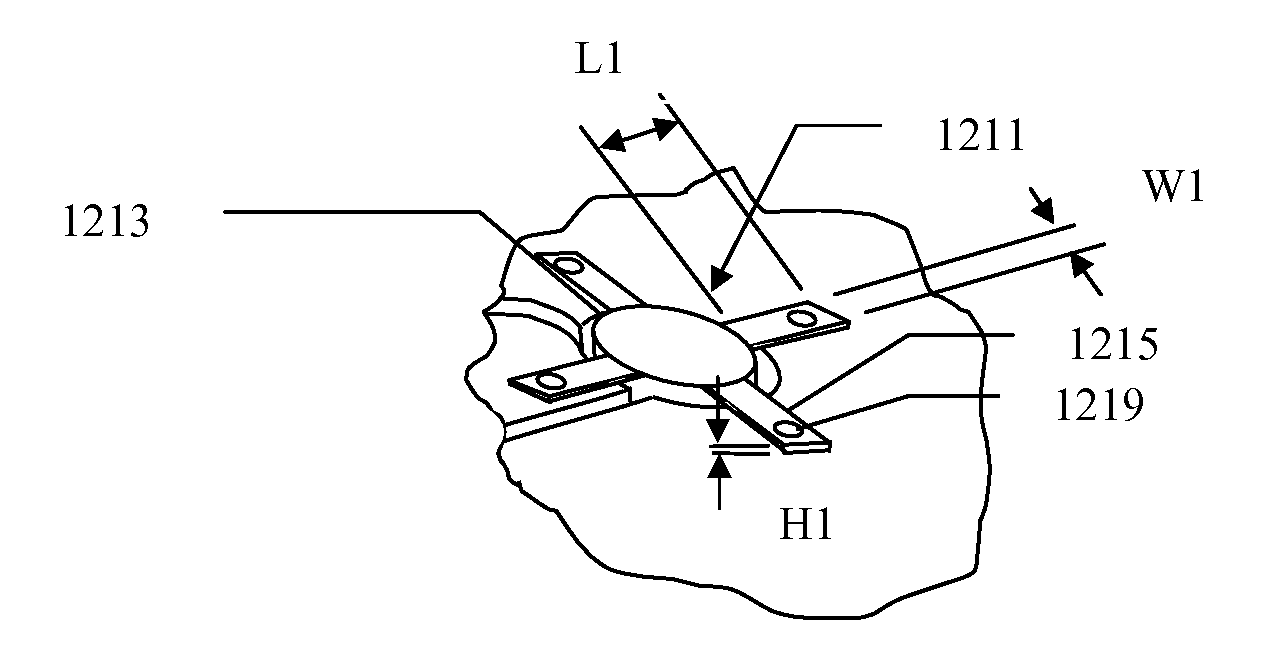
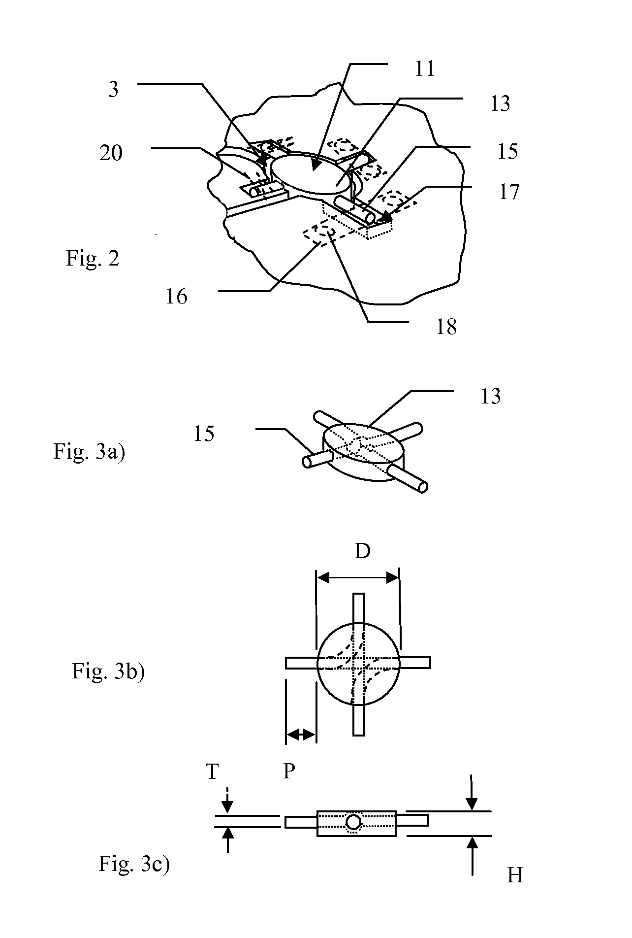
[0033]FIGS. 3a)-3c) shows schematically the implant 11 of FIG. 2 in perspective, plan and side views. Implant 11 has a circular body 13 of diameter D and height H. Preferably D is greater than H. Preferably D is between 8 and 20 mm, more preferably between 9 and 15 mm and even more preferably between 10 and 14 mm. Height H is preferably between 1 and 10 mm, more preferably between 2 and 8 mm and even more preferably between 3 and 6 mm. Protruding substantially radially from body 13 are anchoring wires 15. Each wire protrudes a distance P from body 13 and has a diameter T. Preferably the length of protrusion P is between 2 and 15 mm, more preferably between 3 and 10 mm and even more preferably between 4 and 8 mm. The diameter T of each wire is preferably less than 3 mm, more preferably less than 2 mm and most preferably 1 mm or less. In this example of the invention there are four anchoring wires 15 made from two lengths of wire which cross inside the tile as shown by dotted lines in...

second embodiment

[0034]FIGS. 4 and 5a)-5c) show schematically the present invention in which each anchoring wire 415 extending from the body 413 of the implant 411 is provided with a substantially circular anchoring tile 419 at its distal end. Each anchoring tile has a diameter d and a height h. Preferably d is between 2 and 10 mm, more preferably between 3 and 8 mm and even more preferably between 4 and 6 mm. Height h is preferably between 0.5 and 6 mm, more preferably between 1 and 5 mm and even more preferably between 1.5 and 4 mm. The anchoring tile is intended to be positioned in an anchoring chamber 421 formed at the end of each of the anchoring grooves 417. Preferably d is less than D and h is less than H in order to minimise the amount of material which has to be removed to form anchoring chambers. The arms and / or anchoring tiles are each retained in their grooves by retaining means—not shown—for example via plates and screws and / or clamps and / or sutures or any other fixing means.

third embodiment

[0035]FIGS. 6 and 7a)-5c) show schematically the present invention in which the anchoring wire 615 of the implant 611 form one or more closed loops 623 protruding from the body 613 of the implant. As can be seen in FIG. 7b) a single anchoring wire is formed into a figure of eight shape with its ends almost meeting at the centre of the figure of eight shape. The body 613 of the implant is formed over these ends. The closed loops extend a distance E from the body 613. Preferably E is between 5 and 15 mm, more preferably between 6 and 12 mm and even more preferably between 8 and 10 mm. The anchoring loops are intended to be positioned in suitably formed anchoring grooves 617 which extend from a bore hole 603 and then return to the same bore hole. The arms are each retained in their grooves by retaining means—shown by dashed lines, for example via plates 616 and screws 618 and / or clamps and / or sutures 620 or any other fixing means.


PUM

PropertyMeasurementUnit
heightaaaaaaaaaa
heightaaaaaaaaaa
heightaaaaaaaaaa

Abstract

An implant includes an implant body and a wire or plate anchoring arrangement for filing a bore hole in a skull. The implant will not only provide filling of the bone defect, but also provide fixation of the bone flap. Methods for forming such implants and methods for using the implants for filing a bore hole in a skull are described.

Description

FIELD OF THE INVENTION [0001]The invention relates to surgical implants, methods for making such implants and methods for using such implants to fill holes in bone tissue.BACKGROUND OF THE INVENTION[0002]Craniotomy is a procedure during which a surgeon make a bone flaps and removes it temporarily to access the brain during surgery. The bone flap is formed by first drilling a plurality, usually two to four, of spaced-apart bore holes though the skull of the patients and then cutting through the bone between the bore holes using a saw. At the end of the procedure the bone flap is replace and reattached to the skull, however the bore holes seldom heal and provide no protection to the underlying brain.[0003]Such bore holes that cannot heal can be filled using autograph, allograph or synthetic scaffold materials. Scaffold strategies involve providing metal meshes or porous ceramic materials. Current strategies using metal mesh do not induce tissue healing. Currently used ceramics are uti...

Claims


Application Information

Patent Timeline
Patent Type & Authority Applications(United States)
IPC IPC(8): A61B17/80B29C45/14
CPCA61F2/2875A61B17/688A61F2002/285A61F2002/30576A61F2002/30578A61F2310/00353A61F2/3094A61B17/842A61F2002/2878A61F2002/30878A61F2002/30957
Inventor QWARNSTROM, BOENGSTRAND, THOMAS
Owner OSSDSIGN
Why Eureka
Try Eureka