Transporting device and printing apparatus

a technology of transporting device and printing apparatus, which is applied in the direction of printing, thin material handling, other printing apparatus, etc., can solve the problems of printing image deterioration, printing base material wrinkle generation, and deterioration of printing accuracy, so as to improve the properties that support or protect the base material, improve the properties that support the printing base material, and improve the effect of the transporting accuracy

Active Publication Date: 2016-10-11
SEIKO EPSON CORP
View PDF7 Cites 3 Cited by
  • Summary
  • Abstract
  • Description
  • Claims
  • Application Information

AI Technical Summary

Benefits of technology

[0007][1] According to a first aspect of the invention, a transporting device which transports a belt-shaped base material by considering a longitudinal direction of the base material as a transporting direction is provided. The transporting device includes a first driving roller, a second driving roller, an inter-roller transporting path, and a tension applying portion. The first driving roller can transport the base material in the transporting direction by winding the base material and rotating. The second driving roller is disposed to be closer to a downstream side of the transporting direction than the first driving roller, and can transport the base material in the transporting direction by winding the base material and rotating. The inter-roller transporting path is provided between the first driving roller and the second driving roller, and the base material can be transported therethrough in a state where the base material is suspended in a direction of gravity and bent. The tension applying portion suctions a bent part of the base material from a lower side in the direction of gravity, and applies tension to the base material on the inter-roller transporting path. According to the transporting device of the aspect, by including the inter-roller transporting path through which the base material is transported in a bent state, the control of the tension of the base material or the control of the transporting speed becomes easy, and the properties that control the transporting are improved. In addition, by the tension applied to the base material by the tension applying portion, the properties that support the base material on the inter-roller transporting path are improved.
[0008][2] In the transporting device according to the aspect, a first driven roller which can nip the base material between the first driving roller and the first driven roller, and rotate together with the first driving roller, and a second driven roller which can nip the base material between the second driving roller and the second driven roller, and rotate together with the second driving roller, may be further provided. According to the transporting device of the aspect, the properties that support the base material in the first driving roller and the second driving roller are improved.
[0010][4] In the transporting device according to the aspect, a bent state detection portion which can detect a level of the bending of the base material on the inter-roller transporting path, and a tension control portion which controls a suction force in the tension applying portion in accordance with a detection result by the bent state detection portion, may be further provided. According to the transporting device of the aspect, appropriate tension is applied to the base material in accordance with the level of the bending of the base material on the inter-roller transporting path, and the properties that protect the base material on the inter-roller transporting path are improved.
[0012][6] In the transporting device according to the aspect, a guide portion which regulates a position shift of the base material in the direction which intersects with the transporting direction may be disposed at an inlet through which the base material is fed in between the second driving roller and the second driven roller. According to the transporting device of the aspect, since the position shift of the base material when the base material is guided between the second driving roller and the second driven roller is suppressed, the properties that support or protect the base material are improved.
[0013][7] In the transporting device according to the aspect, the tension applying portion may include a wall portion which surrounds the bent part of the base material, and a negative pressure generation portion which generates negative pressure below the bent part of the base material in the region surrounded by the wall portion. According to the transporting device of the aspect, the tension can be effectively applied to the base material on the inter-roller transporting path.
[0014][8] According to a second aspect of the invention, a printing apparatus which forms a printed image on a belt-shaped printing base material is provided. The printing apparatus includes the transporting device according to any one of the above-described aspects which transports the printing base material as the base material. According to the printing apparatus of the aspect, while improving the properties that control the transporting of the base material, it is possible to improve the properties that support the printing base material which is being transported.

Problems solved by technology

However, in the technology of JP-A-8-311782, since the printing base material is not supported at the section in which the printing base material is loosened, there is a possibility that various defects, such as oscillation of the loosened part of the printing base material, deterioration of the accuracy of the transporting of the printing base material, generation of wrinkles on the printing base material, or deterioration of a printed image, are caused.
Such a problem is a common problem in a transporting mechanism which transports the belt-shaped base material, not being limited to the printing apparatus.

Method used


Image

  • Transporting device and printing apparatus
  • Transporting device and printing apparatus
  • Transporting device and printing apparatus

Examples


first embodiment

Conclusion of First Embodiment

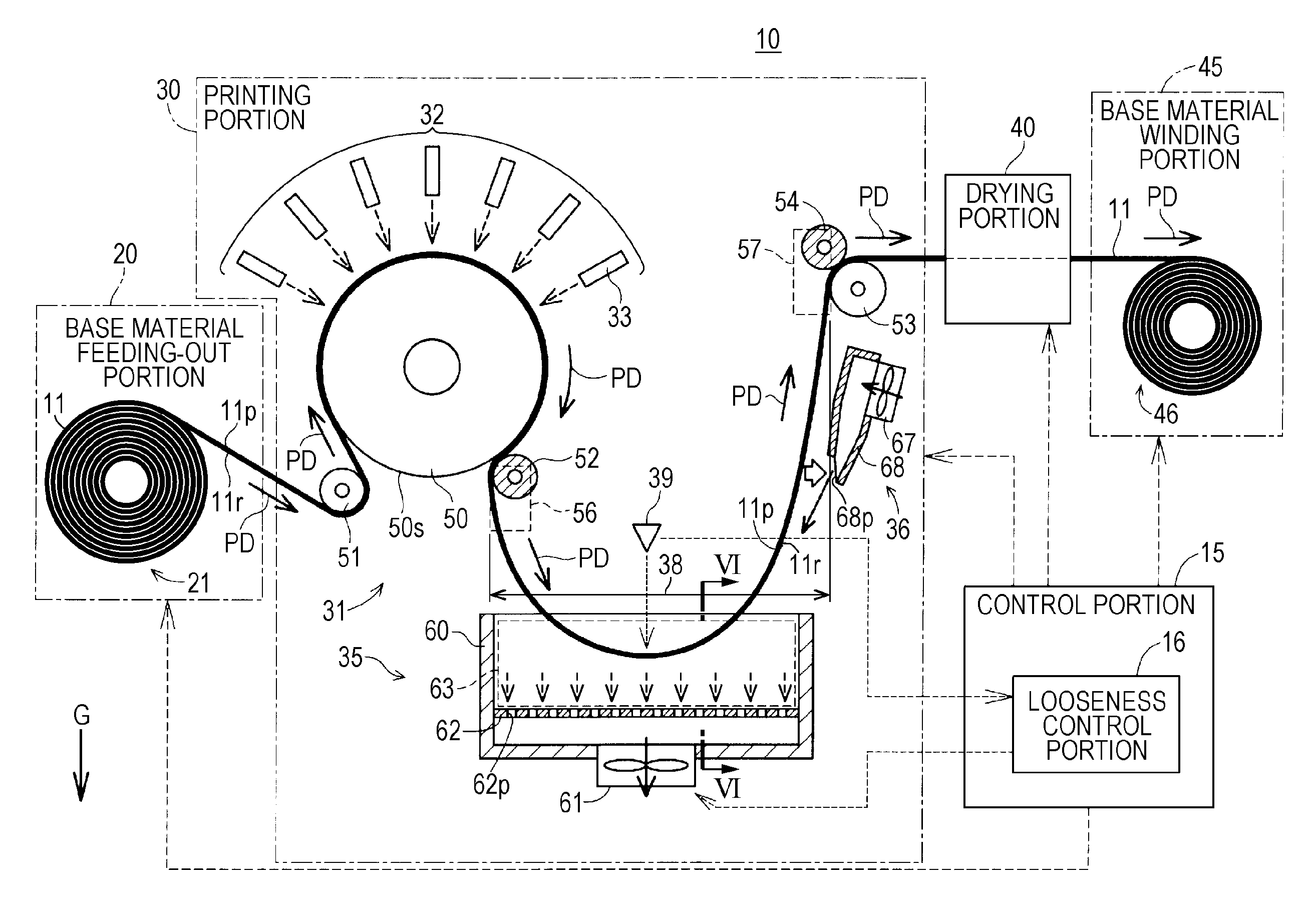
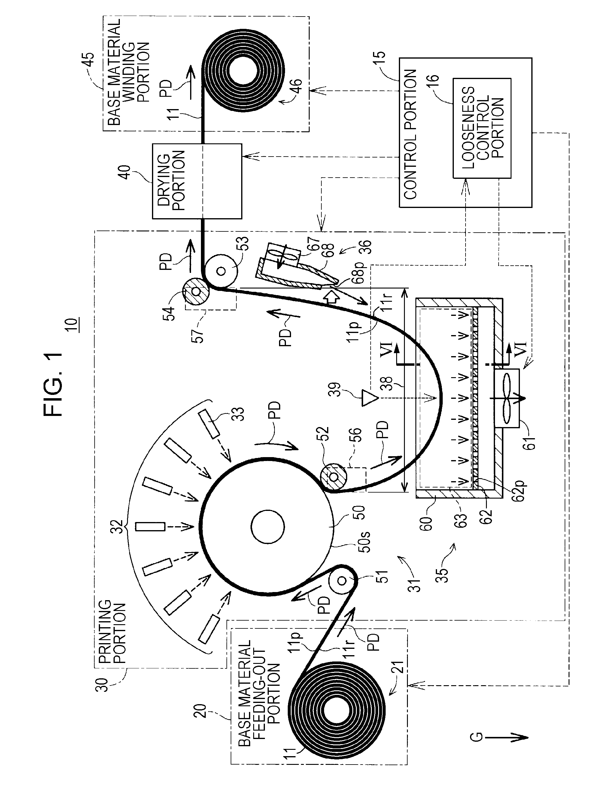
[0082]As described above, according to the printing apparatus 10 of the first embodiment, the properties that control the transporting of the printing base material 11 are improved by including the inter-roller transporting path 38 which makes the printing base material 11 loosened. In addition, the properties that support or protect the printing base material 11 on the inter-roller transporting path 38 are improved by the tension applying portion 35 or the base material suction portion 36, and the properties that protect the printing base material 11 are improved, for example, generation of wrinkles on the printing base material 11 is suppressed. Furthermore, the properties that support the printing base material 11 are improved by the rotating drum 50 and the first driven roller 52 on the upstream side of the inter-roller transporting path 38, and the properties that support the printing base material 11 and the transporting force are improved by the ...

second embodiment

B. Second Embodiment

[0083]A configuration of a printing portion 30A in a printing apparatus of a second embodiment will be described with reference to FIGS. 7 to 9. In the printing apparatus of the second embodiment, when transporting the printing base material 11 in the transporting direction, and when transporting the printing base material 11 in a direction reverse to the transporting direction, the configuration of the transporting mechanism in the printing portion 30A is changed. Hereinafter, for convenience, the transporting direction of the printing base material 11 when forming the printed image as described in the first embodiment is called a “first transporting direction”, and a direction reverse to the first transporting direction is called a “second transporting direction”. In addition, in the following description, the expressions “upstream” and “downstream” are not particularly stated, and mean directions which consider the first transporting direction as a reference, ...

third embodiment

C. Third Embodiment

[0095]FIG. 10 is a schematic view illustrating a configuration of a printing portion 30B in a printing apparatus of a third embodiment. In FIG. 10, for convenience, only the configuration in the vicinity of the rotating drum 50 and the first driven roller 52 in the printing portion 30B of the third embodiment is extracted and illustrated. The printing apparatus of the third embodiment has a configuration which is substantially the same as that of the printing apparatus 10 (FIG. 1) of the first embodiment except that the base material suction portion 36 is added to a side which is closer to the upstream side than the top of the bending of the printing base material 11 on the inter-roller transporting path 38. Hereinafter, the base material suction portion 36 (FIG. 1) which is disposed to be closer to the downstream side than the top of the bending of the printing base material 11 illustrated in the first embodiment is called a “first base material suction portion 3...


PUM

PropertyMeasurementUnit
gravityaaaaaaaaaa
tensionaaaaaaaaaa
bendingaaaaaaaaaa

Abstract

A transporting device which transports a belt-shaped base material by considering a longitudinal direction of the base material as a transporting direction, includes a first driving roller which transports the base material in the transporting direction; a second driving roller which is disposed to be closer to a downstream side of the transporting direction than the first driving roller, and transports the base material in the transporting direction; an inter-roller transporting path which is provided between the first driving roller and the second driving roller, and through which the base material is transported in a state where the base material is suspended in a direction of gravity and bent; and a tension applying portion which suctions a bent part of the base material from a lower side in the direction of gravity, and applies tension to the base material on the inter-roller transporting path.

Description

BACKGROUND[0001]1. Technical Field[0002]The present invention relates to a transporting device and a printing apparatus.[0003]2. Related Art[0004]Among printing apparatuses, there is a printing apparatus which consecutively performs printing while transporting a belt-shaped printing base material which is also called a web (for example, refer to the following JP-A-8-311782). In such a printing apparatus, a transporting speed or tension of the printing base material is controlled and the printing base material is transported in a longitudinal direction by a plurality of rollers. In the technology of JP-A-8-311782, by providing a section in which the printing base material is loosened and transported, it is possible to adjust the transporting speed of the printing base material between configuration portions.[0005]However, in the technology of JP-A-8-311782, since the printing base material is not supported at the section in which the printing base material is loosened, there is a pos...

Claims


Application Information

Patent Timeline
Patent Type & Authority Patents(United States)
IPC IPC(8): B65H23/04B41J15/00B41J15/16B65H23/188
CPCB65H23/044B41J15/005B41J15/16B65H23/188B65H2301/31122B65H2301/517B65H2301/5111B65H2406/311B65H2801/15
Inventor KAWAKAMI, SHINJI
Owner SEIKO EPSON CORP
Why Eureka
Try Eureka