A tensioning device for a frameless microcoil winding machine

A tensioner, skeletonless technology, applied in electrical components, inductance/transformer/magnet manufacturing, circuits, etc., can solve the problem of the large size of the tensioner, the insufficiently compact installation layout, and the large size of mechanical tensioners or electronic tensioners. question

Active Publication Date: 2021-02-19
宁波韵升装备技术有限公司 +2
View PDF6 Cites 0 Cited by
  • Summary
  • Abstract
  • Description
  • Claims
  • Application Information

AI Technical Summary

Problems solved by technology

The pay-off method of the mechanical tensioner or the electronic tensioner is passive and free, so the volume of the mechanical tensioner or the electronic tensioner is relatively large, and the installation layout is not compact enough
The multi-axis frameless microcoil winding machine needs to install multiple tensioning devices to realize the tensioning and straightening of multiple coil winding processes, and the production efficiency is high. The single-axis frameless microcoil winding machine can only install one tensioning device. device, only one frameless microcoil can be wound at a time, and the production efficiency is low
And the tensioning device volume of existing frameless type microcoil winding machine is too large, can't be installed on the multi-axis frameless type microcoil winding machine simultaneously, can only be suitable for uniaxial frameless type microcoil winding machine, so that The production efficiency of the skeletonless microcoil winding machine is low, and it is difficult to realize mass production

Method used


Image

  • A tensioning device for a frameless microcoil winding machine
  • A tensioning device for a frameless microcoil winding machine
  • A tensioning device for a frameless microcoil winding machine

Examples


Embodiment

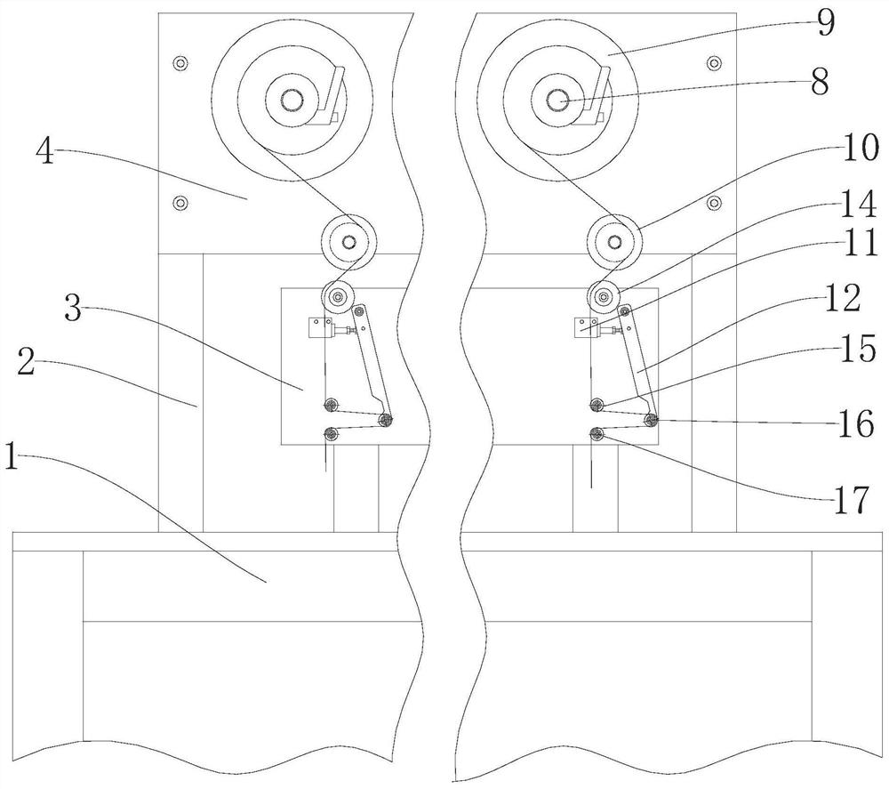
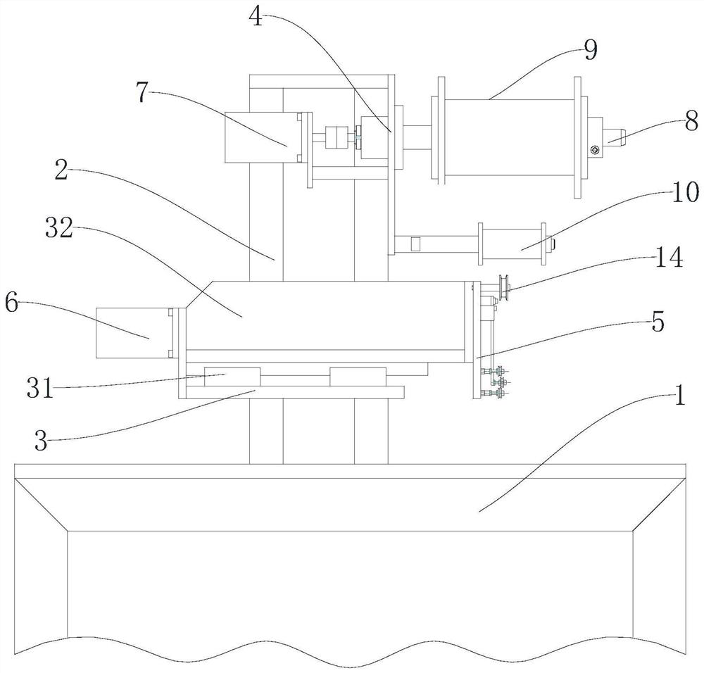
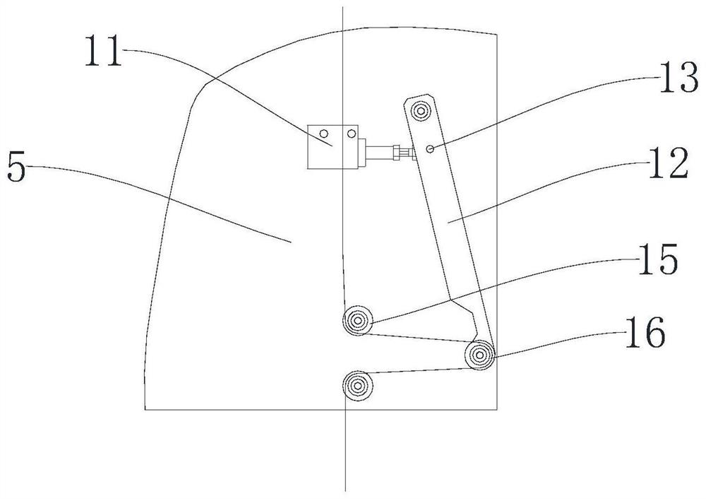
[0014]Embodiment: As shown in the figure, a tensioning device for a frameless microcoil winding machine includes a frame 1, a bracket 2 fixed on the frame 1, an installation platform 3, a first flat plate 4, and a second flat plate 5 , the wire inlet mechanism and the wire outlet mechanism, the installation platform 3 is fixedly arranged on the support 2, the installation platform 3 is provided with a guide rail 31 and the first motor 6, the guide rail 31 is provided with a moving block 32, and the moving block 32 is connected with the first motor 6 , the first motor 6 is used to drive the moving block 32 to move linearly along the guide rail 31, the first flat plate 4 is vertically arranged and fixedly arranged on the support 2, the second flat plate 5 is vertically arranged and fixedly arranged on the moving block 32, and the second flat plate 5 is vertically arranged and fixedly arranged on the moving block 32. The second flat plate 5 is located below the first flat plate 4;...


PUM

PropertyMeasurementUnit
areaaaaaaaaaaa

Abstract

The invention discloses a tensioning device for a frameless micro-coil winding machine, which comprises a frame, a bracket fixed on the frame, an installation platform, a first flat plate, a second flat plate, a wire inlet mechanism and an outlet mechanism, and the installation platform A guide rail and a first motor are arranged on the guide rail, a moving block is arranged on the guide rail, the moving block is connected to the first motor, the first flat plate is vertically arranged and fixedly arranged on the bracket, and the second flat plate is vertically arranged and fixedly arranged on the moving block , the wire inlet mechanism includes n wire inlet assemblies, and each wire inlet assembly includes a rotating member, a spool shaft, a spool, and a first guide wheel, and the wire outlet mechanism includes an electronically controlled servo proportional valve and n wire outlet assemblies, and each wire outlet assembly The components include cylinder, rotating arm, cam bearing follower, second guide wheel, third guide wheel, fourth guide wheel and fifth guide wheel; the advantages are compact structure, small volume, and can be used for multi-axis coil winding The wire machine improves the production efficiency of the skeleton-free microcoil and realizes the mass production of the skeletonless microcoil.

Description

technical field [0001] The invention relates to a tensioning device, in particular to a tensioning device for a frameless microcoil winding machine. Background technique [0002] The enameled wire used in the frameless microcoil is a self-adhesive polyamideimide enameled wire, which is formed by utilizing the self-adhesive property of the self-adhesive polyamideimide enameled wire. Self-adhesive polyamideimide enameled wire has a temperature resistance rating of 220°C, but its cross-sectional area is only 0.0036mm 2 ~0.034mm 2 between. Self-adhesive polyamide-imide enameled wire is different from ordinary enameled wires wound around motors or transformer coils, and has unique material properties. Therefore, a unique tensioning device is required to ensure self-adhesive polyamide-imide The tension of the amine enameled wire during the winding process is straight. [0003] The tensioning device of the existing frameless microcoil winding machine is generally realized by an...

Claims


Application Information

Patent Timeline
Patent Type & Authority Patents(China)
IPC IPC(8): H01F41/094
CPCH01F41/094
Inventor 车方龙赵金波周国强
Owner 宁波韵升装备技术有限公司
Why Eureka
Try Eureka