Cradle cabinet for pull-type radar electronic device

An electronic equipment, pull-out technology, applied in data centers, support structure installation, servers, etc., can solve the problem of conflicting widths, etc., to achieve the effect of improving utilization, easy maintenance, and simple overall structure

Inactive Publication Date: 2018-10-30
BEIJING INST OF RADIO MEASUREMENT
View PDF9 Cites 5 Cited by
  • Summary
  • Abstract
  • Description
  • Claims
  • Application Information

AI Technical Summary

Problems solved by technology

[0002] At present, the traditional radar electronic equipment cradle cabinet refers to a cabinet with a cradle that can rotate around a fixed shaft on one side inside. Convenience and other outstanding advantages, and it is beneficial to improve the generalization and standardization of products; but the traditional cradle cabinet also has certain shortcomings, that is, the larger depth of the cradle and the smaller width of the cabinet are contradictory, that is to say, due to the rotation function of the cradle, Larger cradle depth requirements must require a larger cabinet width, which is in contradiction with the smaller cabinet width requirements. It can be seen that the traditional cradle has the disadvantage of large cabinet width and will occupy more shelter space; therefore, in order to reasonably To solve the contradiction between the larger cradle depth and the smaller cabinet width of the traditional rotating shaft fixed cradle cabinet, and reduce the cabin space occupied by the cabinet as a whole, it is necessary to develop a more compact new cradle cabinet on the basis of the traditional cradle cabinet

Method used


Image

  • Cradle cabinet for pull-type radar electronic device
  • Cradle cabinet for pull-type radar electronic device
  • Cradle cabinet for pull-type radar electronic device

Examples


Embodiment Construction

[0038] The principles and features of the present invention are described below in conjunction with the accompanying drawings, and the examples given are only used to explain the present invention, and are not intended to limit the scope of the present invention.

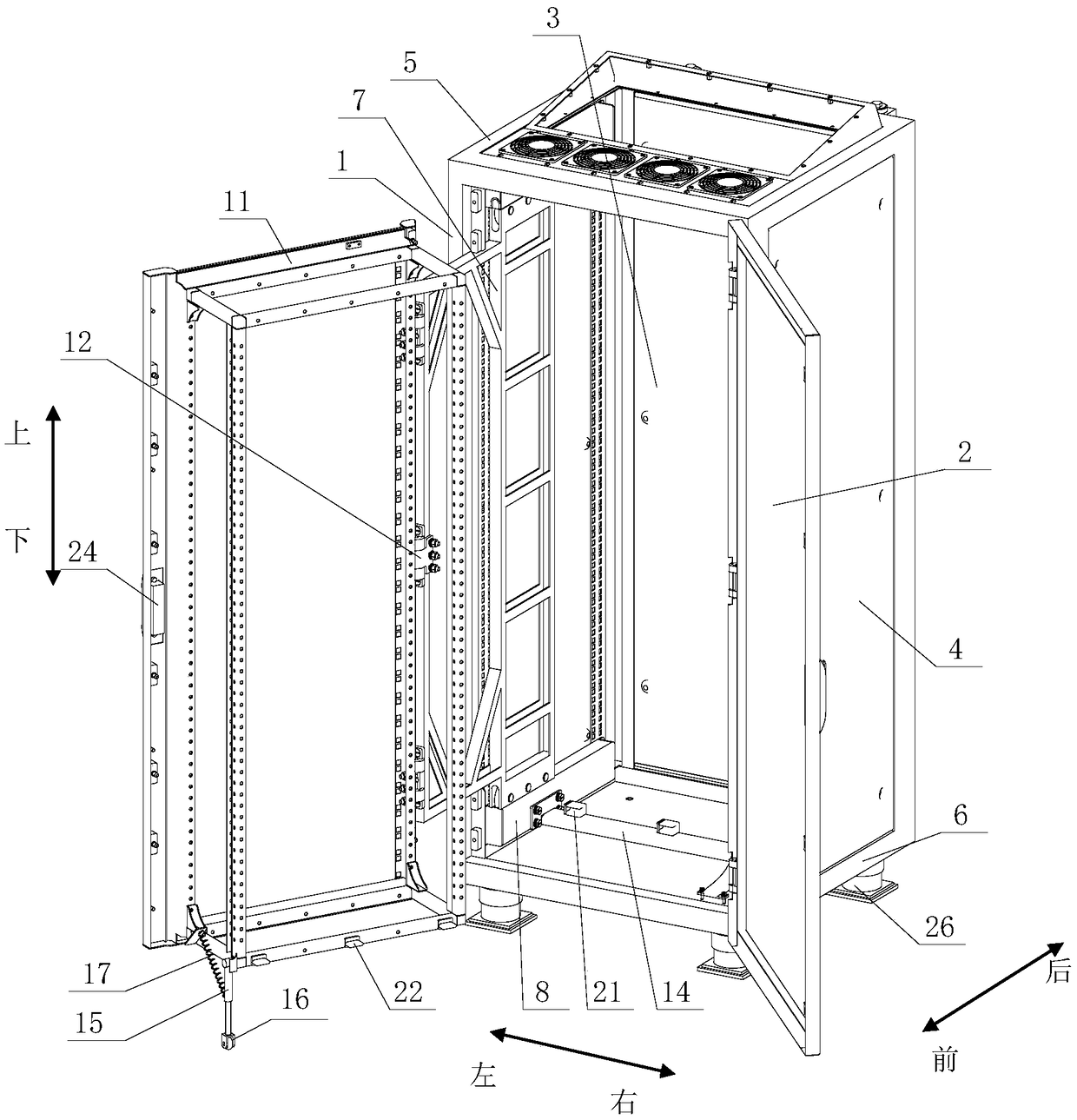
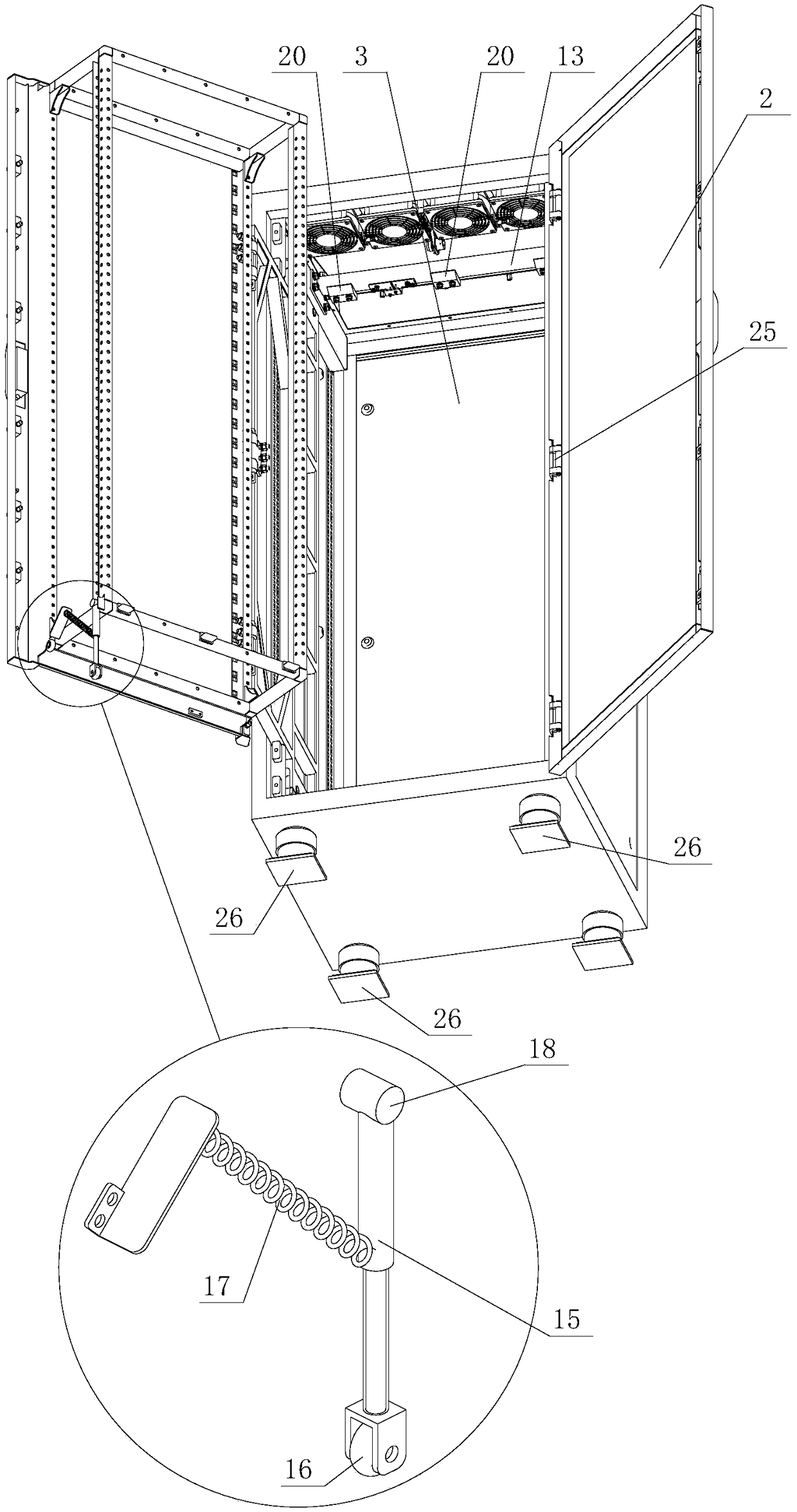
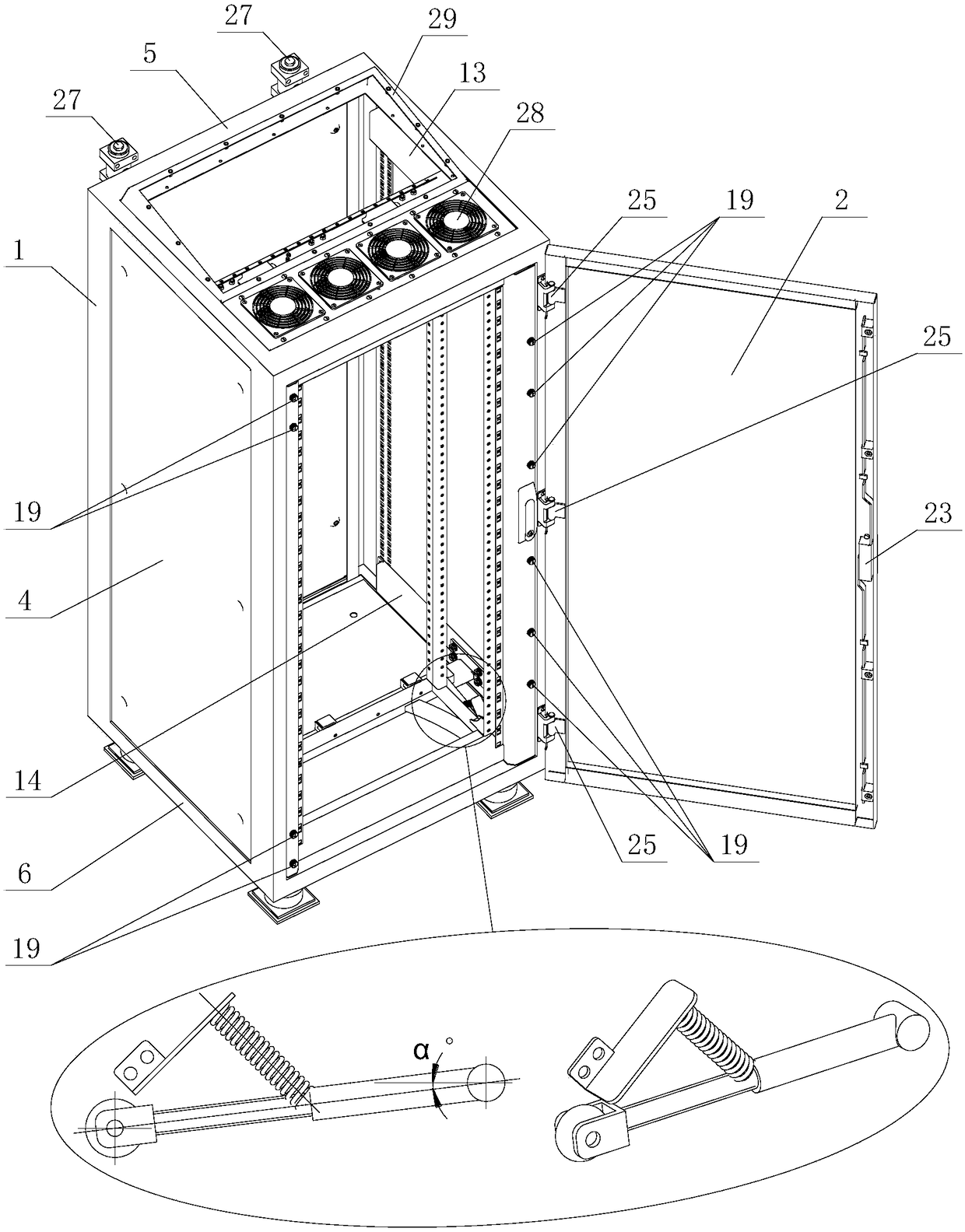
[0039] Such as Figure 1 to Figure 9 As shown, a pull-out cradle cabinet for radar electronic equipment in this embodiment includes: a cabinet main body, a sliding frame assembly, a track beam 8 and a cradle 11; The upper and lower ends of the sliding frame assembly are slidably connected with track beams 8, and the track beams 8 are fixedly connected on the vertical side walls of the accommodating cavity, and the front end of the cradle 11 and the sliding frame assembly is hinged; When sliding, the cradle 11 can be pulled back and forth in the cabinet main body and can rotate around the front end of the sliding frame assembly.

[0040] Specifically, the main body of the cabinet can be a welded shell structure, or ...


PUM


Abstract

The invention relates to a cradle cabinet for a pull-type radar electronic device, comprising: a cabinet body, a sliding frame assembly, track beams and a cradle, wherein the front side of the cabinetbody is provided with an accommodating cavity with an open end, the upper and lower ends of the sliding frame assembly are respectively slidably connected with track beams, the track beams are fixedly connected to the vertical side wall of the accommodating cavity, and the cradle is hinged with the front end of the sliding frame assembly. When the sliding frame assembly slides along the track beams, the cradle may be pumped back and forth by pulling in the cabinet body and rotate around the front end of the sliding frame assembly. The invention solves the contradiction between the large cradle depth and the smaller cabinet width of the conventional rotating shaft fixed cradle cabinet, and reduces the square space occupied by the overall cabinet. The cradle motion form of the pull-type andhinge-type rotation makes the overall structure compact with no maintaining dead angle, has strong system openness, and greatly utilizes the internal space of the cabinet.

Description

technical field [0001] The invention relates to the field of radar electronic equipment cabinets, in particular to a pull-out cradle cabinet for radar electronic equipment. Background technique [0002] At present, the traditional radar electronic equipment cradle cabinet refers to a cabinet with a cradle that can rotate around a fixed shaft on one side inside. Convenience and other outstanding advantages, and it is beneficial to improve the generalization and standardization of products; but the traditional cradle cabinet also has certain shortcomings, that is, the larger depth of the cradle and the smaller width of the cabinet are contradictory, that is to say, due to the rotation function of the cradle, Larger cradle depth requirements must require a larger cabinet width, which is in contradiction with the smaller cabinet width requirements. It can be seen that the traditional cradle has the disadvantage of large cabinet width and will occupy more shelter space; therefore...

Claims


Application Information

Patent Timeline
Patent Type & Authority Applications(China)
IPC IPC(8): H05K7/14
CPCH05K7/1489
Inventor 张建民
Owner BEIJING INST OF RADIO MEASUREMENT
Why Eureka
Try Eureka