Yarn storage device and yarn winding device

A yarn and storage technology, applied in spinning machine, open-end spinning machine, transportation and packaging, etc., can solve problems such as increased manufacturing cost and yarn damage

Inactive Publication Date: 2015-04-15
MURATA MASCH LTD
View PDF7 Cites 0 Cited by
  • Summary
  • Abstract
  • Description
  • Claims
  • Application Information

AI Technical Summary

Problems solved by technology

However, the structure of Patent Document 3 must form a plurality of yarn guides that act elastically toward the outer side of the yarn storage body, and the manufacturing cost increases.
In addition, in the structure of Patent Document 3, since the sheath surface is discontinuous in the circumferential direction at the portion of the yarn guide, it slips at the position of the yarn guide and damages the unwound yarn.

Method used


Image

  • Yarn storage device and yarn winding device
  • Yarn storage device and yarn winding device
  • Yarn storage device and yarn winding device

Examples


Embodiment Construction

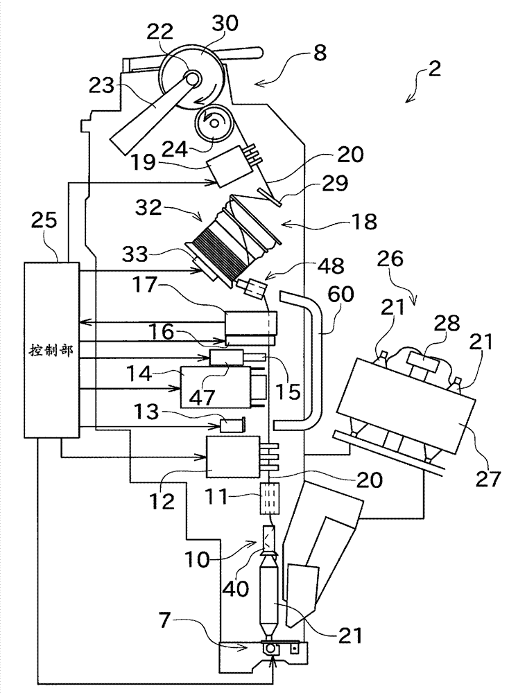
[0055] Next, embodiments of the present invention will be described. figure 1 It is a schematic side view of the winding unit 2 included in the automatic winder as the yarn winding machine according to the first embodiment of the present invention. The automatic winder of the present embodiment has a configuration in which a plurality of winder units 2 are arranged in parallel. In addition, this automatic winder includes a machine management device (not shown) for centrally managing the above-mentioned winding unit 2, and a blower box (not shown) including a compressed air source and a negative pressure source.

[0056] like figure 1 As shown, the winding unit 2 mainly includes a yarn feeding part 7 and a winding part 8 . The winding unit 2 is configured to unwind the yarn (spinning yarn) 20 supported by the yarn supplying bobbin 21 of the yarn supplying section 7 and rewind it to the package 30 . also, figure 1 The appearance of the winder unit 2 during normal winding ...


PUM


Abstract

A yarn accumulation device (18) is configured to wind and accumulate a yarn on a yarn accumulation part (37) that is formed on an outer circumferential surface of a yarn accumulation roller (32), the yarn being unwound from the yarn accumulation part (37) in a direction along a rotation axis of the yarn accumulation roller (32). The yarn accumulation device (18) includes a tension applying part (38). The tension applying part (38) is arranged at an unwinding side of the yarn accumulation part (37). The tension applying part (38) is configured to rotate integrally with the yarn accumulation part (37) and in this condition applies a tension to the yarn being unwound from the yarn accumulation part (37). The tension applying part (38) includes a rubber ring (51) made of an expandable elastic material, and an enlarged / reduced portion (50) provided radially inside the rubber ring (51) and configured such that the yarn is nipped between the enlarged / reduced portion (50) and the rubber ring (51). The enlarged / reduced portion (50) is configured to enlarge or reduce its diameter in accordance with the speed of rotation of the yarn accumulation roller (32).

Description

technical field [0001] The present invention relates to a yarn accumulating device included in a yarn winding machine. Specifically, it relates to a mechanism for applying tension to the yarn unwound from the yarn accumulating device in the yarn accumulating device. Background technique [0002] In yarn winding machines such as textile machines, there is known a yarn accumulating device that temporarily accumulates the yarn by winding the yarn around a rotating yarn accumulating roller. [0003] In such a yarn accumulating device, the yarn wound around the yarn accumulating roller is unwound by pulling out the yarn along an extension of the axis of the yarn accumulating roller. However, since the yarn accumulated in the yarn accumulation roller is helically wound around the outer peripheral surface of the yarn accumulation roller, the yarn drawn from the yarn accumulation roller is Around the braid while wiggling and unwinding. At this time, the trajectory of the unwound ...

Claims


Application Information

Patent Timeline
Patent Type & Authority Patents(China)
IPC IPC(8): B65H51/22B65H59/10D01H13/00D01H13/10
CPCB65H2701/31B65H51/22D01H4/48
Inventor 今村裕司
Owner MURATA MASCH LTD
Why Eureka
Try Eureka