
Filament winding device

a winding device and filament technology, applied in the direction of filament handling, thin material processing, transportation and packaging, etc., can solve the problems of winding failure of fiber bundles on liner, and disparity in fiber bundle tension, so as to reduce the cost of tension adjustment and unreeling failure detection portion, and facilitate the control of the tension of the plurality of fiber bundles. , the effect of easy arrangemen

Active Publication Date: 2017-10-24
MURATA MASCH LTD +1
View PDF15 Cites 0 Cited by
  • Summary
  • Abstract
  • Description
  • Claims
  • Application Information

AI Technical Summary

Benefits of technology

The filament winding device described in this patent has several technical effects. Firstly, it includes a tension adjusting portion and unreeling failure detecting portion that can be miniaturized, reducing costs and making it easier to arrange. The tension adjusting portion can collectively adjust the tension of multiple fiber bundles, providing better control. The unreeling failure detecting portion can accurately detect failure on the bobbin, as it is not attributable to operational failures. Secondly, the device includes a yarn path between the tension adjusting portion and the bobbin, which makes it easy to detect variations in tension caused by unreeling failure on the bobbin. Lastly, the device includes a fiber bundle head that transfers in the axial direction while rotating about the liner, making it easy to simultaneously wind multiple fiber bundles on the liner. The unreeling failure detecting portions can be easily constituted, and can detect unreeling failure on the bobbin with high accuracy.

Problems solved by technology

When the tension applied to the fiber bundles is varied, or the tension between the fiber bundles is not uniform, there is a case where the winding failure of the fiber bundles on the liner occurs.
The disparity in the tension of the fiber bundles, for example, is caused by the unreeling failure of the fiber bundles on the bobbins and the like.

Method used


Image

  • Filament winding device
  • Filament winding device
  • Filament winding device

Examples


first embodiment

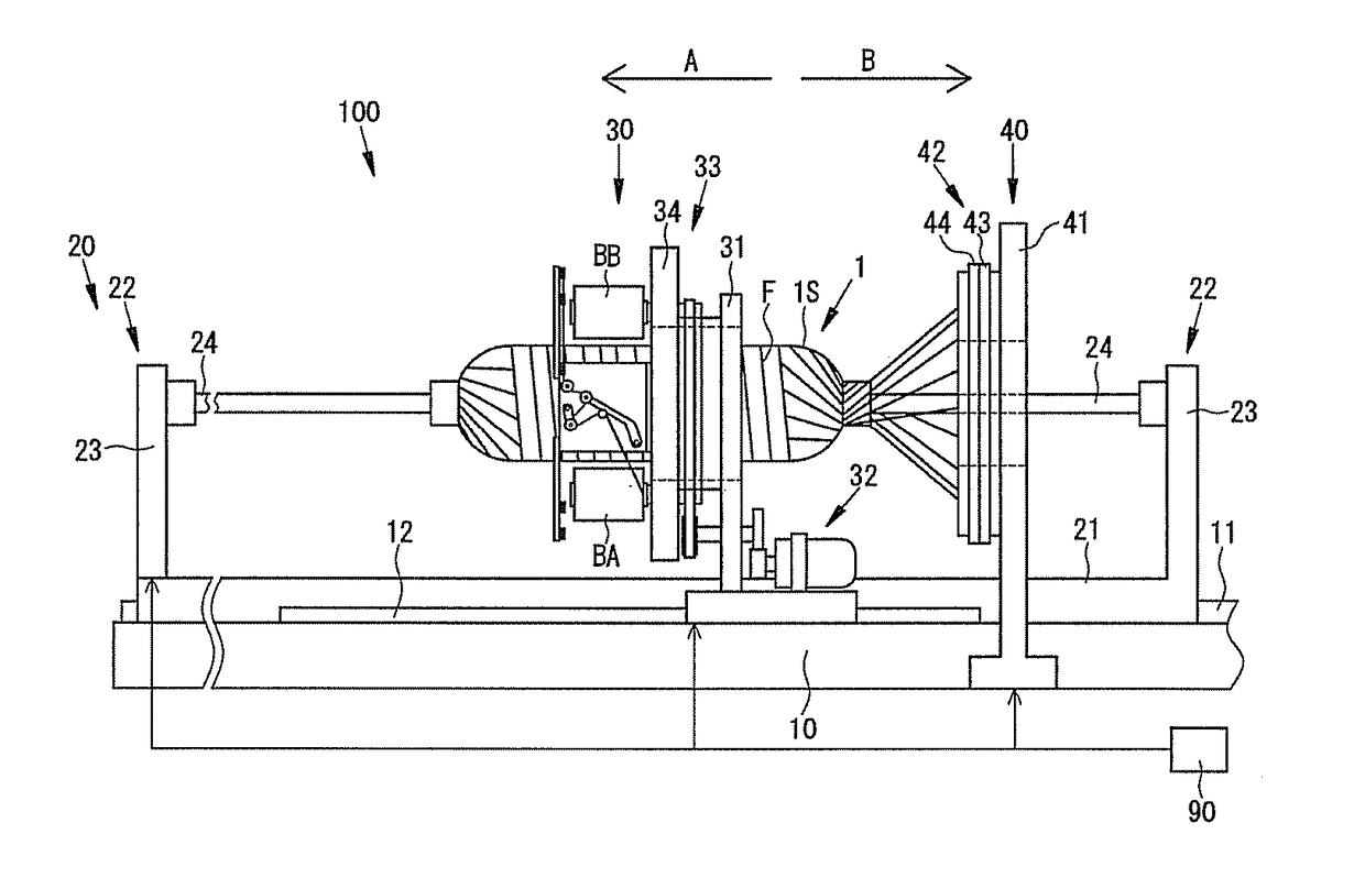
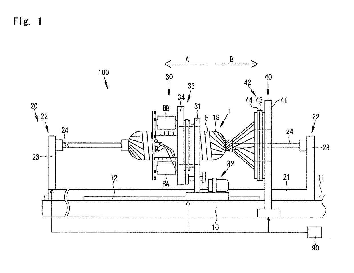
[0045]A filament winding device 100 (hereinafter referred to as “FW device 100”) according to the first embodiment of the present invention will be described. As illustrated in FIG. 1, the FW device 100 is a device that winds a plurality of fiber bundles F, in which resin is impregnated, around the circumference of a liner 1, by repeatedly alternating hoop winding by use of a hoop winding device 30 with helical winding by use of a helical winding device 40 with respect to the liner 1. FIG. 1 illustrates a state where the hoop winding device 30 is disposed at a winding position.

[0046]Arrows A and B illustrated in FIG. 1 represent the back-and-front direction of the FW device 100 and the transfer direction of the liner 1 regarding the helical winding. In the helical winding, the liner 1 is reciprocated in the back-and-front direction of the FW device 100, so that there is a case where the liner 1 is transferred in the direction of the arrow A, and there is a case where the liner 1 is ...

second embodiment

[0100]Next, the second embodiment of the present invention will be described. In the present embodiment, a second tension adjusting portion 210, a second unreeling failure detecting portion 230, and a second tension detecting portion 250 are provided for the helical winding device 40. First, the schematic constitution of these portions will be described.

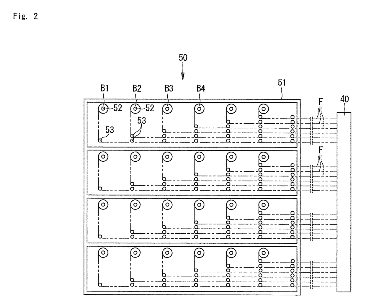
[0101]As illustrated in FIG. 8, the second tension adjusting portion 210, the second unreeling failure detecting portions 230, and the second tension detecting portions 250 are arranged on the yarn paths leading from the plurality of bobbins B1, B2, . . . to the first helical head 43 and the second helical head 44. In the present embodiment, 180 bobbins B1, B2, . . . and B180 are divided into 15 bobbin groups G1, G2, and G15, and each of the bobbin groups G1, G2, . . . and G15 has 12 bobbins B1, B2, . . . , for which the second tension adjusting portion 210, the second unreeling failure detecting portions 230, and the second tension ...


PUM

PropertyMeasurementUnit
winding angleaaaaaaaaaa
tensionaaaaaaaaaa
circumferenceaaaaaaaaaa

Abstract

With regard to a filament winding device in which a plurality of fiber bundles are simultaneously wound around a liner, a tension detecting portion and a tension adjusting portion are miniaturized, the cost of the tension detecting portion and the tension adjusting portion is reduced, and the tension detecting portion and the tension adjusting portion are easily arranged. Provided is a filament winding device 100 that includes a tension adjusting portion 110 that collectively adjusts tension of a plurality of fiber bundles F unreeled from a plurality of bobbins B and an unreeling failure detecting portion 130 that individually detects the unreeling failure of the fiber bundles F on the bobbins B for each bobbin B.

Description

TECHNICAL FIELD[0001]The present invention relates to a technology of a filament winding device.BACKGROUND ART[0002]Conventionally, there have been known filament winding devices (hereinafter appropriately referred to as “FW device”) that include a fiber bundle head that allows a plurality of fiber bundles supplied from a plurality of bobbins to face the outer circumference of a liner and manufacture pressure containers and the like in a manner that the fiber bundle head and the liner are relatively rotated, centering on the axis of the liner, thereby simultaneously winding the plurality of fiber bundles on the liner.[0003]For example, Patent Literature 1 discloses the FW device that includes a hoop winding head in which hoop winding is simultaneously applied to a small number (for example, four or eight) of fiber bundles around the liner, and a helical winding head in which helical winding is simultaneously applied to a multitude (for example, 180) of fiber bundles, as the FW devic...

Claims


Application Information

Patent Timeline
Patent Type & Authority Patents(United States)
IPC IPC(8): B65H63/00B65H59/32B29C53/80B29C53/60B65H63/06
CPCB29C53/602B29C53/8016B65H63/061B65H59/32B65H2701/31B29C2053/8025
Inventor TANIGAWA, MOTOHIROUOZUMI, TADASHINAKAMURA, DAIGOROHATTA, KEN
Owner MURATA MASCH LTD
Learn More