
Shaping device of plastic thin film production equipment and plastic thin film shaping method

A plastic film and production equipment technology, applied in the field of plastic film production, can solve the problems of short heating time, poor shaping effect, small bonding area between metal roller and plastic film, etc., and achieve the effect of direct action

Active Publication Date: 2013-10-02
汕头市光华机械实业有限公司
View PDF2 Cites 0 Cited by
  • Summary
  • Abstract
  • Description
  • Claims
  • Application Information

AI Technical Summary

Problems solved by technology

[0005] The first one is in the form of an oven. Although there are many metal rollers in the oven, these metal rollers are all at the same horizontal position. When working, the plastic film passes over each metal roller, which is equivalent to the thickness of the film. Standing on the metal roller, this measure has the following disadvantages: 1. From a geometric point of view, the surface of the metal roller and the surface of the plastic film form a tangent geometric relationship, so the bonding surface between the metal roller and the plastic film is extremely small , the close contact is not close, and it is difficult for the metal roller to transfer heat to the plastic film. The plastic film needs to go through a long stroke to be heated to the required temperature. Compared with the main machine of the film machine, the temporary space for the setting device is much larger; 2. It is difficult for the surface of the metal roller in the oven to form pressure and tension on the film, and it is impossible to use the smooth surface of the metal roller to affect the surface of the film under heat. For trimming, besides, the metal roller can only touch one side of the plastic film, and cannot touch the two sides of the plastic film; in addition, it is not conducive to controlling the tension of the plastic film;
There are also disadvantages in this form: 1. As mentioned above, the shaping device cannot use multiple heat-conducting rollers, but only one to two heat-conducting rollers. Due to the small number of heat-conducting rollers and the short and rapid heating time, the setting effect is poor, and In order to heat the plastic film to a certain temperature, it is also required that the temperature of the heat conduction roller is very high, so it is easy to burn the film. If you want to reduce the temperature of the heat conduction roller, the heating effect will be weakened and the shaping effect will be affected; 2. The heating device is not sealed, The energy consumption of heating is relatively large, which has a great influence on the temperature of the production workshop
[0008] However, no matter which of the above two forms, neither can have the advantages of both at the same time.

Method used


Image

  • Shaping device of plastic thin film production equipment and plastic thin film shaping method
  • Shaping device of plastic thin film production equipment and plastic thin film shaping method
  • Shaping device of plastic thin film production equipment and plastic thin film shaping method

Examples


Embodiment 1

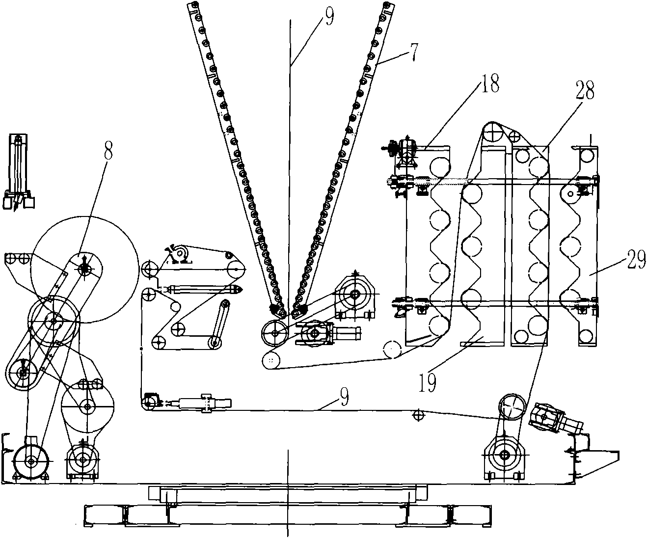
[0035] figure 1 The sizing device of the plastic film production equipment shown is applied in the film blowing machine and is arranged next to the herringbone plate 7 of the film blowing machine. There is also a winding device 8 in the film blowing machine, and the winding device is equipped with a tension control mechanism.

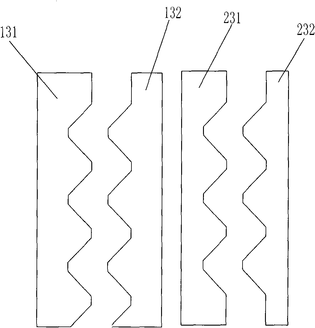
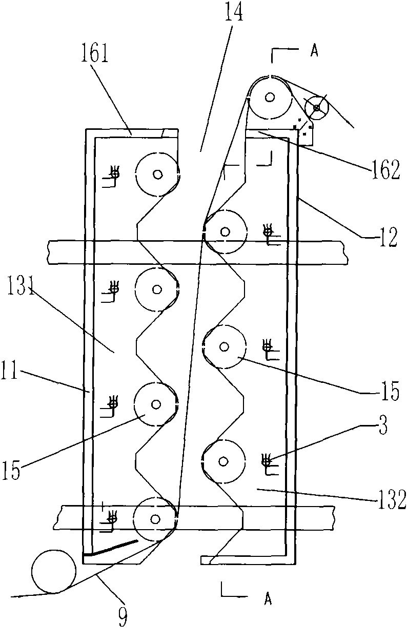
[0036] figure 1 , Figure 5 , Figure 8 As shown, the sizing device includes a heating box 1 and a cooling box 2; figure 2 , image 3 , Figure 4 , Figure 5 As shown, the heating box 1 is provided with a front wall 11, a rear wall 12, and two left and right side walls, and the left and right side walls are formed by engagement of the front half 131 and the rear half 132 respectively. The shape of the front half of the left side wall is the same as that of the right side The front half of the wall is the same shape, the second half of the left wall is the same shape as the second half of the right wall, figure 2 Show the shape of the front hal...

Embodiment 2

[0040] In this embodiment, the front unit and the rear unit of the heating box are movably installed on the track by means of rollers, and the front unit and the rear unit of the cooling box are movably installed on the track by means of rollers. The driving mechanism for the back and forth movement of the rear unit, the front unit of the cooling box, and the rear unit of the cooling box. All the other are the same as the first embodiment.

Embodiment 3

[0042] A plastic film shaping method, adopting the shaping device of the plastic film production equipment described in Embodiment 1, comprises the following steps in turn: (1), before the plastic film is formed, utilize the screw mandrel driving mechanism of the heating box 1 to turn the heating box The front unit and the rear unit are pulled apart, so that a vertical through-slit 14 that runs up and down appears between the front unit and the rear unit of the heating box, such as figure 1 , image 3 Shown; (2), after plastic film 9 is just moulding, traction plastic film passes through the vertical slot 14 between heating box front unit and rear unit, as figure 1 , image 3 Shown; (3), the driving mechanism of heating box pulls the front unit and rear unit of heating box together, makes the first two halves 131 and the rear half 132 of each side wall of heating box engage and splice together, makes the front half of heating box top plate The part 161 and the second half pa...


PUM


Abstract

The invention discloses a shaping device of plastic thin film production equipment. The shaping device comprises a heating box and a cooling device, wherein side walls on the two sides of the heating box are formed by engaging and splicing a front part and a rear part respectively; the splicing part of the front part and the rear part of the side wall on each side is tooth-shaped; the front half parts of the side walls on the two sides are integrally connected with a front wall to form a front unit; the rear half parts of the side walls on the two sides are integrally connected with a rear wall to form a rear unit; a driving mechanism for driving the front unit or the rear unit to move back and forth along a track is also provided; the front unit and the rear unit of the heating box are provided with a plurality of horizontal metal rollers respectively; and the metal rollers of the front unit and the rear unit are vertically arranged at intervals. The invention also provides a plastic thin film shaping method. Through the device and the method, a plastic thin film can be heated in a relatively sealed space and continuously bent and wound through the plurality of metal rollers in the space, so the shaping quality of the plastic thin film is improved.

Description

technical field [0001] The invention belongs to the technical field of plastic film production, and in particular relates to a shaping device of plastic film production equipment and a plastic film shaping method. Background technique [0002] During the production process of plastic film, the molten plastic melt is extruded from the mold to form a plastic film (a film bubble is formed when it is extruded from the mold of the blow molding machine, and the film bubble is further inflated to form a film), and the film is solidified after cooling. Finally, it is wound up by a winding shaft. In order to further improve the quality of the plastic film, make the shrinkage rate of the plastic film more stable and the surface smoother, after the film is cooled and solidified, and before winding, the plastic film must be heated by a shaping device, and then cooled after heating. The above heating and then cooling process is called the setting process; in the setting process, the str...

Claims


Application Information

Patent Timeline
Patent Type & Authority Patents(China)
IPC IPC(8): B29C71/02
Inventor 李新忠
Owner 汕头市光华机械实业有限公司
Learn More