
Floating roll device for photogravure press

A technology of gravure printing machine and floating roller, which is applied to printing machines, rotary printing machines, printing, etc., and can solve the problems that the floating roller device cannot be placed arbitrarily, the space requirement of the floating roller device is high, and the tension control accuracy is affected. The effect of balanced adjustment, small tension fluctuation, and easy tension control

Pending Publication Date: 2018-03-02
ZHONGSHAN SOTECH PRINTING MACHINERY CO LTD
View PDF8 Cites 0 Cited by
  • Summary
  • Abstract
  • Description
  • Claims
  • Application Information

AI Technical Summary

Problems solved by technology

[0002] Due to the influence of gravity, the floating roller device used for gravure printing machines on the market can only be installed vertically, and the angle of the floating roller device cannot be placed arbitrarily, resulting in high space requirements for the floating roller device, and the floating The gravity of the roller affects the tension control, resulting in large tension fluctuations and poor tension control accuracy; and the swing arm and the rotating shaft are fixed by pinning, which makes assembly and adjustment difficult; in addition, the cylinder swing resistance is large, which affects the tension control accuracy

Method used


Image

  • Floating roll device for photogravure press
  • Floating roll device for photogravure press

Examples


Embodiment Construction

[0020] The present invention will be further described below in conjunction with accompanying drawing:

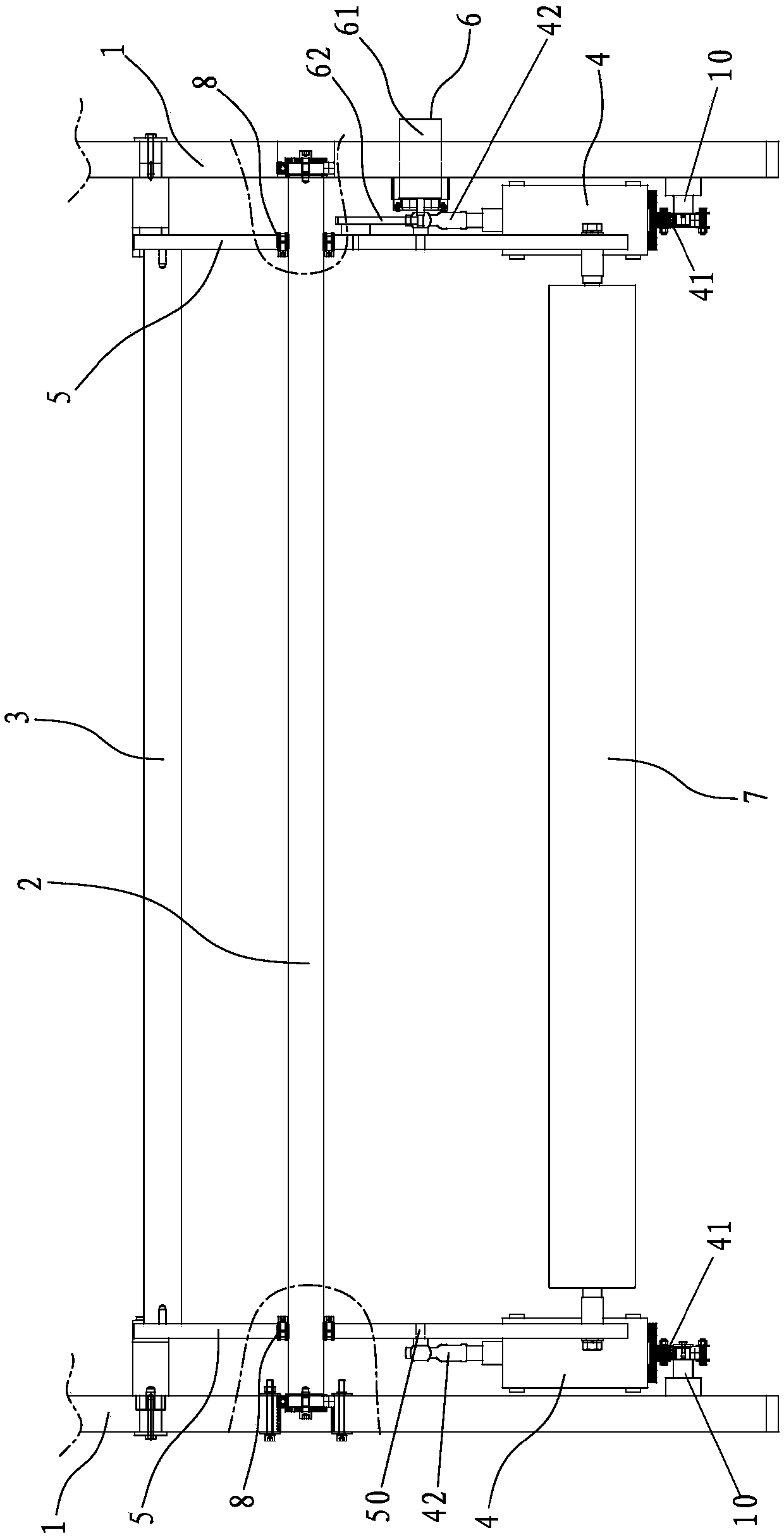
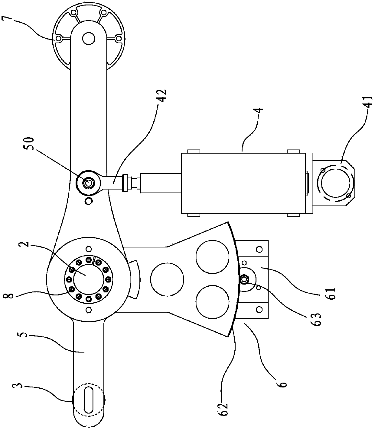
[0021] Such as Figure 1 to Figure 2 The floating roller device shown in the gravure printing machine is characterized in that it includes a rotating shaft 2 arranged on the frame 1, and two swing arms 5 that can follow the rotation of the rotating shaft 2 are respectively provided at both ends. On the swing arm 5 and on both sides of the rotating shaft 2 are respectively connected floating rollers 7 and counterweight rods 3, the floating rollers 7 and the counterweight rods 3 are parallel to the rotating shaft 2, and the swing arm 5 and the frame 1 is provided with a cylinder 4, the cylinder base of the cylinder 4 and the frame 1 are provided with a first rotating device connecting the two and allowing the two to rotate relative to each other, the piston rod of the cylinder 4 and the swing arm 5 There is a second rotating device connecting the two and allowing them to rot...


PUM


Abstract

The invention discloses a floating roll device for a photogravure press. The floating roll device comprises a rotary shaft arranged on racks. The two ends of the rotary shaft are provided with two swing arms capable of rotating along with the two ends of the rotary shaft correspondingly, a floating roll and a balance weight lever are connected to the positions, on the two sides of the rotary shaft, of the swing arms correspondingly, the floating roll and the balance weight lever are parallel to the rotary shaft, and air cylinders are arranged between the swing arms and the racks; first rotating devices used for enabling air cylinder seats of the air cylinders to be connected with the racks and allowing the air cylinder seats of the air cylinders and the racks to rotate oppositely are arranged between the air cylinder seats of the air cylinders and the racks, second rotating devices used for enabling piston rods of the air cylinders to be connected with the swing arms and allowing the piston rods of the air cylinders and the swing arms to rotate oppositely are arranged between the piston rods of the air cylinders and the swing arms, and the connection points of the air cylinders andthe swing arms are located between the floating roll and the rotary shaft; the floating roll and the balance weight lever are arranged on the two sides of the rotary shaft correspondingly, the gravity influence of the floating roll and the swing arms can be reduced by the balance weight lever, gravitational equilibrium is adjusted, the angle of the floating roll device can be freely set, so thattension control over a printed material by the floating roll device is easier, and the precision is higher.

Description

【Technical field】 [0001] The invention relates to a dancer roller arrangement for a gravure printing machine. 【Background technique】 [0002] Due to the influence of gravity, the floating roller device used for gravure printing machines on the market can only be installed vertically, and the angle of the floating roller device cannot be placed arbitrarily, resulting in high space requirements for the floating roller device, and the floating The gravity of the roller affects the tension control, resulting in large tension fluctuations and poor tension control accuracy; and the swing arm and the rotating shaft are fixed by pinning, making assembly and adjustment difficult; in addition, the cylinder swing resistance is large, which affects the tension control accuracy. [0003] The present invention is made based on this situation. 【Content of invention】 [0004] The purpose of the present invention is to overcome the deficiencies of the prior art and provide a floating roll...

Claims


Application Information

Patent Timeline
Patent Type & Authority Applications(China)
IPC IPC(8): B65H5/06B41F13/02
CPCB65H5/06B41F13/02B65H2801/03
Inventor 郭景松贺志磐黄亚东吴文秋孟宗发秦启雄
Owner ZHONGSHAN SOTECH PRINTING MACHINERY CO LTD
Learn More